Configuration of Multi-Network Services
(Original Document)
At a Glance
In a station that supports various network modules, each network connection point is considered as an address for the station. When configuring each module, it is necessary to define the list of network numbers that are accessible for each connection point.
Depending on the processor selected during hardware configuration, a bridge station can only manage 3 or 4 network modules. The table will therefore have a maximum of 4 elements.
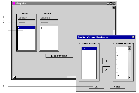
Illustration
A specific screen allows entry of routing data for all the network modules of a station.
Elements and Functions
The following table describes the various zones in the configuration screen:
Label
Field
Function
1
Logical network
Used to display the logical network name.
2
Network type
Used to display the network type.
3
Accessible networks
Used:
  • for the unshaded Logical Network zone, to enter the list of networks accessible by this module,
  • for the shaded Logical Network zones, to display the list of networks accessible by these modules.
4
Available networks
Used to select the networks accessible by a module configured as a bridge.
A list of numbers from 1 to 127 shows the networks available for a connection point. Each network number selected as being accessible is removed from the list of available networks in order to avoid configuration errors.