

At a Glance
XXMIT supports the following ASCII communication functions
Terminated ASCII Input
Simple ASCII Input
ASCII String Messaging
Modbus Port Configuration
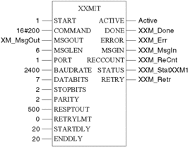
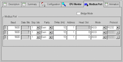
XXMIT function is configured through its Function Block. The Function Block initializes the Modbus port 1 every time it is active, with the defined parameters. The XXMIT parameters can be displayed in the controller’s LCD display.
Example of XXMIT Function Block configuration:
Example of CPU Configuration screen with different value set:
Example of settings on controller’s LCD display:
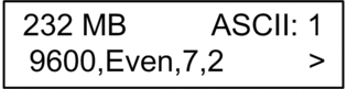
The 3 graphics above show different values for XXMIT function. Regardless of what is set or displayed in the CPU configuration screen or on the LCD display, the actual values used for transmission are the one from the XXMIT Function Block:
Baudrate: 2400
Parity: Even
Data Bits: 7
Stop Bits: 2
Terminated ASCII Input Function
When Bit 11 of the Command Word is activated for terminated ASCII Input messages, the MsgOut array has to contain the ASCII input definition table. Depending of which datatype you selected for MsgOut, the terminated ASCII definition table consists of three words or 6 bytes. The terminated ASCII input definition table is shown in the table below.
Terminated ASCII Input Definition Table (Datatype WordArray)
Word |
High Byte |
Low Byte |
|---|---|---|
MsgOut[1] |
Number of starting characters (allowed content = 0, 1, 2) |
Number of terminator characters (allowed content = 1, 2) |
MsgOut[2] |
First starting character |
Second starting character |
MsgOut[3] |
First terminator character |
Second terminator character |
Terminated ASCII Input Definition Table (Datatype ByteArray)
Byte |
Function |
|---|---|
MsgOut[1] |
length of start string (0 or 1 or 2) |
MsgOut[2] |
length of termination string (1 or 2) |
MsgOut[3] |
1st start character |
MsgOut[4] |
2nd start character |
MsgOut[5] |
1st termination character |
MsgOut[6] |
2nd termination character |
During the process, RecCount holds a running count of characters written into the MsgIn array. Once the terminated string is received the Done output on XXMIT goes ON and RecCount holds the total length of the received string including the starting and terminator strings. At this point XXMIT still owns the port and continues to save newly received characters into the ASCII receive FIFO, because the enable ASCII receive FIFO Command Word, Bit 7 is ON.
Using program logic, you can clear the simple ASCII input Bit before the next scan, while leaving the enable ASCII receive FIFO Bit ON. Thus, MsgIn is NOT over written by newer FIFO data, which is still collected in the FIFO.Using program logic, you can clear both bits for enable ASCII receive FIFO (Bit 7), and terminated ASCII input (Bit 11) to return port control back to the PLC.
When too many characters are written into the MsgIn array with NO terminator detected, or the MsgIn array is outside the allowed range for the configured PLC an error is reported in Status and the RecCount parameter is not significant. The character limit is the smaller of 1024 or two times the sizes of the MsgIn array.
Terminated ASCII Example
Assume that XXMIT is activated with the command word Bit 7 and 11 set. Enable ASCII FIFO and terminated ASCII. The following ASCII string is received by the port: "AMScrlf$weight = 1245 GRAMScrlf$wei". Refer to the ASCII Input Definition Table that shows the contents denoted by ( ) used in this example.
Terminated ASCII Input Definition Table (content Datatype Byte Array)
Byte |
Content |
|---|---|
MsgOut[1] |
Number of starting characters (0x01) |
MsgOut[2] |
Number of terminator characters (0x02) |
MsgOut[3] |
First starting character ('$') |
MsgOut[4] |
Second starting character (Not Used) |
MsgOut[5] |
First terminator character ('cr') |
MsgOut[6] |
Second terminator character ('lf'') |
Terminated ASCII Input Definition Table Example (content for Datatype Word Array)
Word |
High Byte |
Low Byte |
|---|---|---|
MsgOut[1] |
Number of starting characters (0x01) |
Number of terminator characters (0x02) |
MsgOut[2] |
First starting character ('$') |
Second starting character (Not Used) |
MsgOut[3] |
First terminator character ('cr') |
Second terminator character ('lf'') |
XXMIT becomes ACTIVE and then discards from the input FIFO the initial five characters, "AMScrlf", because they do not match the first starting character set to '$'. On the logic scan after the '$' is received, XXMIT remains ACTIVE and it copies the '$' and subsequent characters into the MsgIn array, updating RecCount with the count done so far, as the characters come in.
After the final termination character is received the output Done is activated and MsgLen contains the total length equal to 22 characters (0x0016). The MsgIn array contains: "$weight = 1245 GRAMScrlf" as Byte Array (or: "$w", "ei", "gh", "t ", "= ", "12", "45", " G", "RA", "MS", "crlf" if using a Word Array).
On the scan that the output Done is activated, the already received characters from the next message, "$wei", that came in after the termination string, remains in the ASCII input FIFO. This gives the program logic the opportunity to turn off the Terminated ASCII input before the next scan solve of XXMIT for this port, keeping those characters in the FIFO until the PLC completes processing the current message, that might take several scans.
Simple ASCII Input Function
All incoming characters are placed into the MsgIn array. If MsgIn is defined as Byte Array (as recommended), the incomming characters are simply stored first character into first array element, second character into second and so on.If MsgIn is defined as WordArray, two characters are stored in each element. The first character is stored in the low byte of the first element. The second character is stored in the high byte of the first element. The third character is stored in the high byte of the second element, and so on. The Message Length variable (MsgLen) contains the length of the message (1 ... 1024 characters).
ASCII String Messaging
When Command Word, Bit 9 is activated for String Messaging, the MsgOut array has to contain the ASCII information to be transmitted. The message length MsgLen has to be set to the length of the message to be transmitted.
As mentioned in Detailed Parameter Description, MsgOut may be of any datatype. For ASCII String Messaging the type ByteArray reflects best the nature of strings: First Byte contains first character and so on. (For more information See Simple ASCII Send)
Transmit - Receive Transition
If your application requires to receive an answer from another device after transmitting a message (request - response), you need XXMIT to switch from transmit mode to receive mode in order to read the communication partner’s response. The earliest point in time to switch XXMIT from transmit to receive is the cycle following the transmit operation. It is the responsibility of the user to ensure that the response is delayed by at least one cycle time of the requesting PLC to avoid communication failure.
The transmit delay on the communication partner’s side is especially important in cases of long cycle times on the requester’s side and fast communication partners.
Timing considerations for the Partner Delay-time:
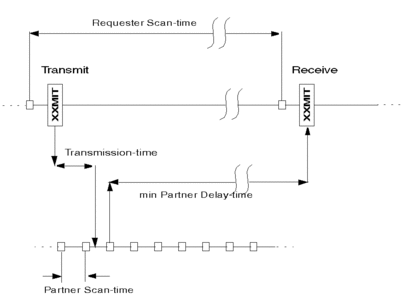
From the above figure (not to scale) you can estimate the influence of the three different times Requester Scan-time, Transmission-time and Partner Scan-time on the required Partner Delay-time. As the requester’s and partner’s scans are asynchronous, the Partner Scan-time should not be taken into account. The transmission-time depends on telegram length and baud rate. A message with 18 characters at 9600 baud takes 14 ms. The main contribution obviously comes from the Requester Scan-time. So even the minimum Partner Delay-time could be less than the Requester Scan-time, we recommend to use the Requester Scan-time as the minimum Partner Delay-time to ensure a sound communication.