Interface Cable Pinouts
You need to build an interface cable between your PLC and the modem or printer. The actual cable is connected to the Port which is supported by the PLC and to the RS232 port of the modem or printer, or direct to another PLC's Modbus port. Because the XXMIT supports many modems and printers the pinouts are going to vary. Some pinouts are provided below.
9-pin (RS-232) to 25-pin (Modem) with no RTS/CTS Control
Refer to the figure for Front Views of Connectors.
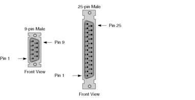
Refer to the Connector Pinouts table.
Connector Pinouts |
||||
|---|---|---|---|---|
9-Pin Connector |
25-Pin D-shell |
|||
Signal Name |
Pinout |
Pinout Connected To ... |
Pinout |
Signal Name |
RXD |
2 |
Yes |
3 |
RXD |
TXD |
3 |
Yes |
2 |
TXD |
RTS |
7 Jumpered 8 Jumpered |
4 Jumpered 5 Jumpered |
RTS |
|
CTS |
CTS |
|||
DSR |
4 Jumpered 6 Jumpered |
6 Jumpered 20 Jumpered |
DSR |
|
DTR |
DTR |
|||
GND |
5 |
Yes |
7 |
GND |
9-pin (RS-232) to 25-pin (Modem) with RTS/CTS Control
Refer to the figure for Front Views of Connectors.
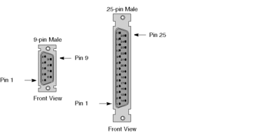
Refer to the Connector Pinouts table.
Connector Pinouts |
||||
|---|---|---|---|---|
9-Pin Connector |
25-Pin D-shell |
|||
Signal Name |
Pinout |
Pinout Connected To ... |
Pinout |
Signal Name |
RXD |
2 |
Yes |
3 |
RXD |
TXD |
3 |
Yes |
2 |
TXD |
RTS |
7 |
Yes |
4 |
RTS |
CTS |
8 |
Yes |
5 |
CTS |
DSR |
4 Jumpered 6 Jumpered |
6 Jumpered 20 Jumpered |
DSR |
|
DTR |
DTR |
|||
GND |
5 |
Yes |
7 |
GND |
9-pin to 9-pin (Null Modem)
Refer to the figure for Front Views of Connectors.

Refer to the Connector Pinouts table.
Connector Pinouts |
||||
|---|---|---|---|---|
9-Pin Connector |
9-Pin Connector |
|||
Signal Name |
Pinout |
Pinout Connected To ... |
Pinout |
Signal Name |
RXD |
2 |
Yes |
3 |
TXD |
TXD |
3 |
Yes |
2 |
RXD |
RTS |
7 Jumpered 8 Jumpered |
7 Jumpered 8 Jumpered |
RTS |
|
CTS |
CTS |
|||
DSR |
4 Jumpered 6 Jumpered |
4 Jumpered 6 Jumpered |
DSR |
|
DTR |
DTR |
|||
GND |
5 |
Yes |
5 |
GND |
9-pin to 9-pin (Modem)
Refer to the figure for Front Views of Connectors.

Refer to the Connector Pinouts table.
Connector Pinouts |
||||
|---|---|---|---|---|
9-Pin Connector |
9-Pin Connector |
|||
Signal Name |
Pinout |
Pinout Connected To ... |
Pinout |
Signal Name |
TXD |
2 |
Yes |
2 |
TXD |
RXD |
3 |
Yes |
3 |
RXD |
RTS |
7 |
Yes |
7 |
RTS |
CTS |
8 |
Yes |
8 |
CTS |
DSR |
4 Jumpered 6 Jumpered |
4 Jumpered 6 Jumpered |
DSR |
|
DTR |
DTR |
|||
GND |
5 |
Yes |
5 |
GND |
9-pin to 25-pin (Null Modem)
Refer to the figure for Front Views of Connectors.
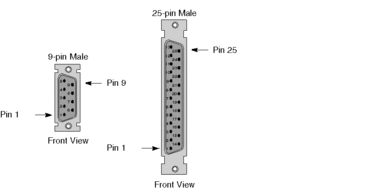
Refer to the Connector Pinouts table.
Connector Pinouts |
||||
|---|---|---|---|---|
9-Pin Connector |
25-Pin D-shell |
|||
Signal Name |
Pinout |
Pinout Connected To ... |
Pinout |
Siignal Name |
RXD |
2 |
Yes |
2 |
TXD |
TXD |
3 |
Yes |
3 |
RXD |
RTS |
7 Jumpered 8 Jumpered |
4 Jumpered 5 Jumpered |
RTS |
|
CTS |
CTS |
|||
DSR |
4 Jumpered 6 Jumpered |
6 Jumpered 20 Jumpered |
DSR |
|
DTR |
DTR |
|||
GND |
5 |
Yes |
7 |
GND |
RJ45-(8x8) to 25-pin (Null Modem) 110XCA20401
Refer to the figure for Front Views of Connectors.
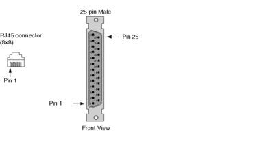
Refer to the Connector Pinouts table.
Connector Pinouts |
||||
|---|---|---|---|---|
RJ45 Connector |
25-Pin D-shell |
|||
Signal Name |
Pinout |
Pinout Connected To ... |
Pinout |
Signal Name |
RXD |
4 |
Yes |
2 |
TXD |
TXD |
3 |
Yes |
3 |
RXD |
RTS |
6 Jumpered 7 Jumpered |
4 Jumpered 5 Jumpered |
RTS |
|
CTS |
CTS |
|||
GND |
5 |
Yes |
7 |
GND |
DSR |
2 |
Yes |
6 20 |
DSR |
DTR |
||||
Chassis Ground |
8 |
Yes |
1 |
Chassis Ground |
N.C.(*) |
1 |
No |
||
(*) 5 Vdc delivered by the controller. Do not connect |
||||
| WARNING | |
|---|---|
RJ45-(8x8) to 9-pin (Null Modem) 110XCA20301
Refer to the figure for Front Views of Connectors.

Refer to the Connector Pinouts table.
Connector Pinouts |
||||
|---|---|---|---|---|
RJ45 Connector |
9-Pin D-shell |
|||
Signal Name |
Pinout |
Pinout Connected To ... |
Pinout |
Signal Name |
RXD |
4 |
Yes |
3 |
TXD |
TXD |
3 |
Yes |
2 |
RXD |
RTS |
6 Jumpered 7 Jumpered |
7 Jumpered 8 Jumpered |
RTS |
|
CTS |
CTS |
|||
GND |
5 |
Yes |
5 |
GND |
DSR |
2 |
Yes |
4 6 |
DTR |
DSR |
||||
Chassis Ground |
8 |
Yes |
Case of the Connector |
|
N.C.(*) |
1 |
No |
||
(*) 5 Vdc delivered by the controller. Do not connect |
||||
| WARNING | |
|---|---|
RJ45-(8x8) to 25-pin (Modem) 110XCA20401
Refer to the figure for Front Views of Connectors.
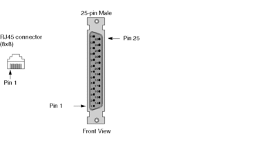
Refer to the Connector Pinouts table.
Connector Pinouts |
||||
|---|---|---|---|---|
RJ45 Connector |
25-Pin D-shell |
|||
Signal Name |
Pinout |
Pinout Connected To ... |
Pinout |
Signal Name |
RXD |
4 |
Yes |
3 |
RXD |
TXD |
3 |
Yes |
2 |
TXD |
RTS |
6 Jumpered 7 Jumpered |
4 Jumpered 5 Jumpered |
RTS |
|
CTS |
CTS |
|||
GND |
5 |
Yes |
7 |
GND |
DSR |
2 |
Yes |
6 20 |
DSR |
DTR |
||||
Chassis Ground |
8 |
Yes |
1 |
Chassis Ground |
N.C.(*) |
1 |
No |
||
(*) 5 Vdc delivered by the controller. Do not connect |
||||
| WARNING | |
|---|---|
RJ45-(8x8) to 25-pin (Modem) 110XCA20401
Refer to the figure for Front Views of Connectors.
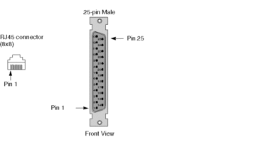
Refer to the Connector Pinouts table.
Connector Pinouts |
||||
|---|---|---|---|---|
RJ45 Connector |
25-Pin D-shell |
|||
Signal Name |
Pinout |
Pinout Connected To ... |
Pinout |
Signal Name |
RXD |
4 |
Yes |
3 |
RXD |
TXD |
3 |
Yes |
2 |
TXD |
RTS |
6 |
Yes |
4 |
RTS |
CTS |
7 |
Yes |
5 |
CTS |
GND |
5 |
Yes |
7 |
GND |
6 Jumpered 20 Jumpered |
DSR |
|||
DTR |
||||
Chassis Ground |
8 |
Yes |
1 |
Chassis Ground |
N.C.(*) |
1 |
No |
||
(*) 5 Vdc delivered by the controller. Do not connect |
||||
| WARNING | |
|---|---|
RJ45-(8x8) to RJ45-(8x8) (Modem)
Refer to the figure for Front Views of Connectors.

Refer to the Connector Pinouts table.
Connector Pinouts |
||||
|---|---|---|---|---|
RJ45 Connector |
RJ45 Connector |
|||
Signal Name |
Pinout |
Pinout Connected To ... |
Pinout |
Signal Name |
RXD |
4 |
Yes |
4 |
RXD |
TXD |
3 |
Yes |
3 |
TXD |
RTS |
6 |
Yes |
6 |
RTS |
CTS |
7 |
Yes |
7 |
CTS |
GND |
5 |
Yes |
5 |
GND |
DSR |
2 |
Yes |
2 |
DSR |
Chassis Ground |
8 |
Yes |
8 |
Chassis Ground |
N.C.(*) |
1 |
No |
||
(*) 5 Vdc delivered by the controller. Do not connect |
||||
| WARNING | |
|---|---|
9-pin to RJ45-(8x8) (Modem) 110XCA20301
Refer to the figure for Front Views of Connectors.

Refer to the Connector Pinouts table.
Connector Pinouts |
||||
|---|---|---|---|---|
RJ45 Connector |
9-Pin Connector |
|||
Signal Name |
Pinout |
Pinout Connected To ... |
Pinout |
Signal Name |
RXD |
4 |
Yes |
2 |
RXD |
TXD |
3 |
Yes |
3 |
TXD |
RTS |
6 Jumpered 7 Jumpered |
7 Jumpered 8 Jumpered |
RTS |
|
CTS |
CTS |
|||
GND |
5 |
Yes |
5 |
GND |
DSR |
2 |
Yes |
6 4 |
DSR |
DTR |
||||
Chassis Ground |
8 |
Yes |
Case of the Connector |
|
N.C.(*) |
1 |
No |
||
(*) 5 Vdc delivered by the controller. Do not connect |
||||
| WARNING | |
|---|---|
9-pin to RJ45-(8x8) (Modem) 110XCA20301
Refer to the figure for Front Views of Connectors.

Refer to the Connector Pinouts table.
Connector Pinouts |
||||
|---|---|---|---|---|
RJ45 Connector |
9-Pin Connector |
|||
Signal Name |
Pinout |
Pinout Connected To ... |
Pinout |
Signal Name |
RXD |
4 |
Yes |
2 |
RXD |
TXD |
3 |
Yes |
3 |
TXD |
RTS |
6 |
Yes |
7 |
RTS |
CTS |
7 |
Yes |
8 |
CTS |
GND |
5 |
Yes |
5 |
GND |
6 Jumpered 4 Jumpered |
DSR |
|||
DTR |
||||
Chassis Ground |
8 |
Yes |
Case of the Connector |
|
N.C.(*) |
1 |
No |
||
(*) 5 Vdc delivered by the controller. Do not connect |
||||
| WARNING | |
|---|---|
RJ 45 High end CPU RS 422/RS 485
Refer to the figure for front view of the CPU Connector.

Pinouts table for the RJ 45 High end Quantum RS 422/RS 485 connector.
Pin |
RS-422 signal |
RS-485 signal |
|---|---|---|
1 |
RX - |
D - |
2 |
RX + |
D + |
3 |
TX + |
|
4 |
Nc |
Nc |
5 |
GND |
GND |
6 |
TX - |
|
7 |
Nc |
Nc |
8 |
Optional PE |
Optional PE |


