|
Creating the Project
|
|
|
(Original Document)
|
|
Step
|
Action
|
|---|---|
|
1
|
Launch the Control Expert software,
|
|
2
|
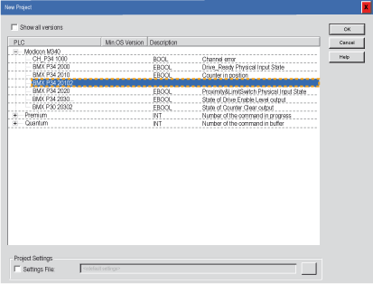
Click on File then New to select a BMX P34 20102 processor:
 |
|
3
|
Confirm with OK.
|
|
Step
|
Action
|
|---|---|
|
1
|
In the Project Browser double-click on Configuration then on 0:PLC Bus and on 0:BMX XBP ••• (Where 0 is the rack number),
|
|
2
|
In the PLC Bus window, select a slot (for example slot 1) and double-click on it,
|
|
3
|
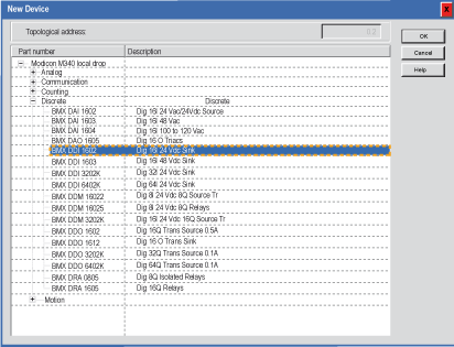
Choose the BMX DDI 1602 discrete input module located in the Discrete modules list,
 |
|
4
|
Confirm with OK.
|
|
Step
|
Action
|
|---|---|
|
1
|
In the Project Browser double-click on Configuration then on 0:PLC Bus and on 0:BMX XBP ••• (Where 0 is the rack number),
|
|
2
|
In the PLC Bus window, select a slot (for example slot 1) and double-click on it,
|
|
3
|
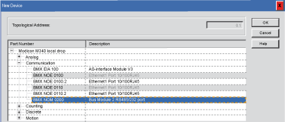
Choose the BMX NOM 0200 communication module located in the Communication modules list,
 |
|
4
|
Confirm with OK.
|
|
Step
|
Action
|
|---|---|
|
1
|
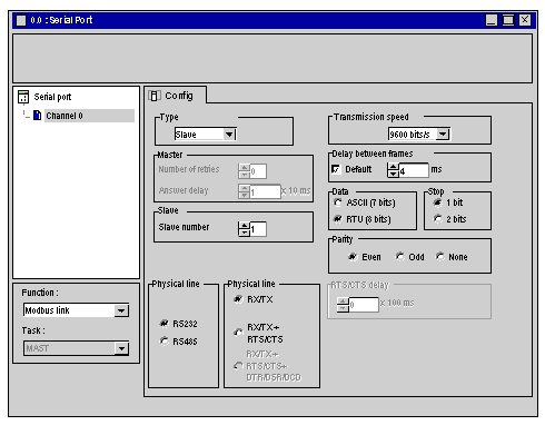
In the Project Browser double-click on Configuration then on 0:BMX XBP 0800 then on 0:BMX P34 20102. Then double click on Serial Port to access to the 0.0:Serial Port window.
 |
|
2
|
Select the Slave type.
|
|
3
|
Select 9600 bits/s for transmission speed.
|
|
4
|
Select RS232 for physical line.
|
|
5
|
Select RTU (8bits) for data type.
|
|
6
|
Close the window and confirm with OK.
|
|
Step
|
Action
|
|---|---|
|
1
|
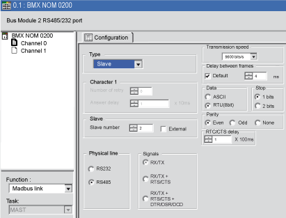
In the Project Browser double-click on Configuration then on 0:BMX XBP 0800 then on 0:BMX NOM 0200 to access to the 0.x:BMX NOM 0200 window (where x is the slot number, for example x=1).
 |
|
2
|
Select the Channel 0.
|
|
3
|
Select the Modbus link for function.
|
|
4
|
Select the Slave type.
|
|
5
|
Select 9600 bits/s for transmission speed.
|
|
6
|
Select RS232 for physical line.
|
|
7
|
Select RX/TX + RTS/CTS + DTR/DSR/DCD for signals.
|
|
8
|
Select 100 ms for RTS/CTS delay.
|
|
9
|
Select RTU (8bits) for data type.
|
|
10
|
Close the window and confirm with OK.
|