The following pages present two examples of Modbus devices connection and a Modbus serial link architecture.
Connecting Modbus Devices that are Powered via the Serial Link
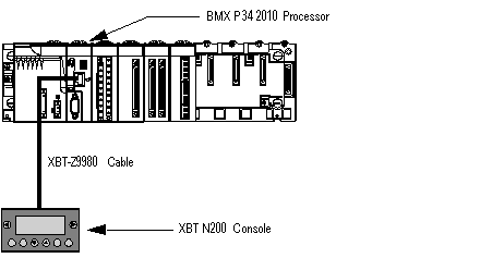
The illustration below shows how a BMX P34 2010 processor is connected to an XBT N200 console powered by the Modbus serial link:
The devices are configured as follows:
-
The BMX P34 2010 processor is configured as slave,
-
The XBT N200 human-machine interface is configured as master.
The XBT-Z9980 cable has the following properties:
Connecting Modbus Devices that are not Powered via the Serial Link
This architecture consists of the following elements:
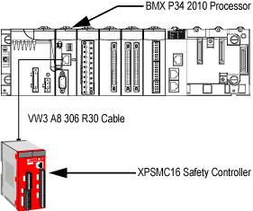
The illustration below shows how a BMX P34 2010 processor is connected to an XPSMC16 safety controller:
The devices are configured as follows:
-
The BMX P34 2010 processor is configured as master,
-
The XPSMC16 safety controller is configured as slave.
The VW3 A8 306 R30 cable has the following properties:
Modbus Serial Link Architecture
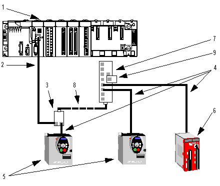
The Modbus serial link architecture consists of the following elements:
-
A BMX P34 2010/20102 processor configured as master,
-
An XPSMC16 safety controller configured as slave,
-
A TWDXCAISO isolated splitter block,
-
An LU9 GC3 splitter block,
-
Two ATV31 drives, configured as slaves.
The diagram below represents the serial link architecture described above:
1
BMX P34 2010 processor
2
XBT-Z9980 cable
3
TWDXCAISO isolated splitter block
4
VW3 A8 306 R30 cable
5
ATV31 drive
6
XPSMC16 safety controller
7
LU9 GC3 splitter block
8
TSXCSAx00 cable
9
VW3 A8 306 RC Modbus Line Terminator 

