The Character Mode debug screen is accessible in online mode.
Accessing the Debug Screen
The following table describes the procedure for accessing the debug screen for Character Mode communication:
|
Step
|
Action
|
|
1
|
|
|
2
|
Select the "Debug" tab on the screen that appears.
|
Description of the Debug Screen
The debug screen consists of an Error zone and a Signals zone.
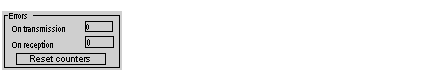
The Error zone looks like this:
This zone indicates the number of communication interruptions counted by the processor:
The Reset Counters button resets both counters to zero.
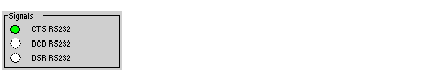
The Signals zone looks like this:
This zone indicates the activity of the signals:
-
CTS RS232: shows the activity of the CTS signal.
-
DCD RS232: not managed by the processor (no activity on this LED).
-
DSR RS232: not managed by the processor (no activity on this LED).