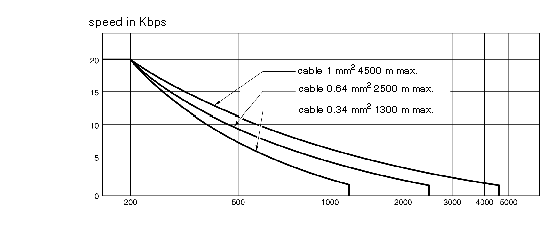
The flow of a current loop link is limited by the cross-section and the length or the cable used.
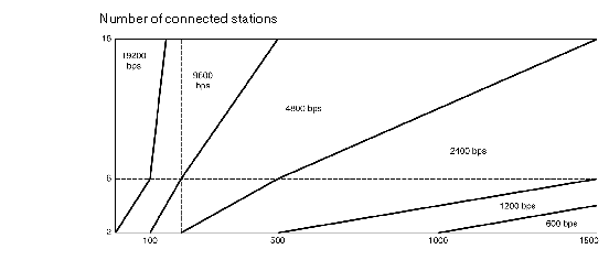
The user should refer to the two charts below to evaluate the performance which can be obtained using this application.
These curves are given for a shielded two pair cable (send through one pair, reception through the other) while observing all the precautions of use.
The chart below is given for a shielded cable with a conductor cross-section of 0.34 mm2. The connection is made according to the parallel multidrop diagram below. Using conductors with a larger cross-section improves the quality of the signals transmitted:
Multidrop link performance is optimized when there are more connected stations. The line is busier, which improves the quality of the transmitted signal.
When the connection is made according to the
diagram above, the number of stations can be increased artificially (to a maximum of 16 stations) by loading the line at one of its ends.
This can be carried out by incorporating a load resistance.
This load resistance can be connected to any junction block providing it is between pins 17 and 19 of cards TSX SCP 112.
The value of Lr resistance simulating the load of "N" stations is determined by the formula:
Example:
An installation is physically made up of 6 stations connected in multidrop with an external 24 V supply.
The performance of the line is that of 10 stations, simulating the load of 4 additional stations by a resistance:
NOTE: The load resistance must not have an inductive effect or there is a risk that it will not operate.
Use a thick layer of resistance.


