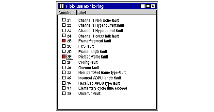
This screen provides the user with a global view of the bus and signals communication faults occurring on the bus.
The screen lists all the communication fault counters and signals any change in their value.
The device screen looks like this:
Each line contains:
-
an icon showing the state of the fault counters (the reference state being the state they were in when the screen was opened):
-
the counter number in hexadecimal,
-
the counter label (as specified by the WORLDFIP standard).
While the screen is open, the report variables of all connection points are read cyclically.
When the screen is opened or upon reset, the values of the counters for each report variable are stored to constitute a reference state. The time between two reads of the same variable is equal to the number of devices configured + 2 (0 and 63) in seconds.
As soon as a fault counter changes its value from its reference value, for any connection point, the counter icon changes to red. Reading the counter label provides details of the type of fault detected.
Example
Counter 21 changes to red. This means that at least one counter 21 of all the counters 21 has changed its value.
How to Reset the Reference State
The following procedure describes how to reset the reference state.
|
Step
|
Action
|
|
1
|
Right click on the background.
Result: a shortcut menu appears.
|
|
2
|
Select the Reset command.
|
Bus Monitoring by the Application
In Control Expert, the system words %SW150 and %SW151 indicate the number of frames sent and received by the channel manager.
If these two counters have stopped this indicates the Fipio channel manager function has stopped.
This is signaled to the user in the configuration screen in online mode by the connection point 0 shown in red.

