|
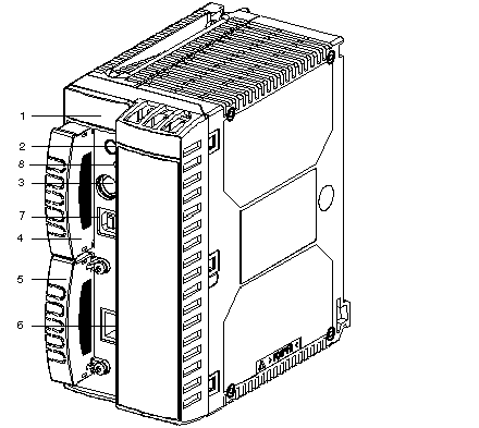
Physical Description of the TSX P57 6634/5634/4634 Processors
|
|
|
Original instructions
|

|
Number
|
Function
|
|---|---|
|
1
|
Display block consisting of 6 LEDs
|
|
2
|
Button for requesting removal of the PCMCIA SRAM card (and a DOS file or ATA in the future)
This button must be pressed before removing the card; an LED shows the request status.
|
|
3
|
(TER connector (8-pin mini-DIN)) terminal port:
This is used to connect an FTX or PC-compatible terminal, or to connect the PLC to the Uni-Telway bus via the TSX insulating unit TSX P ACC 01. This connector enables the peripheral connected to it to be supplied with a 5V current (within the limit of the available current provided by the power supply).
|
|
4
|
Slot for an extended memory card in PCMCIA type 1 format
If there is no memory card, this slot is equipped with a cover that it advisable to leave in place to protect the connectors from dust or splashes.
|
|
5
|
Slot for a communication card in PCMCIA type 3 format enabling a Fipio Agent, Uni-Telway, series link, Modbus, Modbus Plus, etc. communication channel to be connected to the processor.
This slot can also hold a SRAM data card or an ATA card in the future.
If there is no communication card, this slot is equipped with a cover.
|
|
6
|
RJ45 connector for Ethernet connection
|
|
7
|
USB port
|
|
8
|
The RESET button activated with a pencil point that triggers a cold start of the PLC when used.
|