A Premium Hot Standby system can be configured in many ways. Below are two examples of Premium Hot Standby topology.
Connecting the ETY Modules
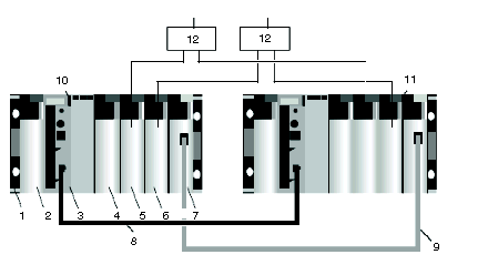
The illustration below displays a simple Premium Hot Standby configuration two ETY modules connected by an Ethernet cable; no switches are used.
1
Premium rack with line terminators
2
Power supply
3
Hot Standby processor (TSX H57 24M or TSX H57 44M)
4
Communication module (TSX SCY 21601 with Modbus PCMCIA TSX SCP 114)
5
Discrete output module (i.e. TSX DSY 64T2K)
6
Discrete input module(i.e. TSX DEY 64D2K)
7
ETY 4103/5103 (minimum firmware version 4.0)
8
CPU sync link cable
9
ETY sync link cable
10
Primary PLC (A)
11
Standby PLC (B)
12
Connection block
The link between the two ETY modules is called the ETY-sync link. The two ETYs are called monitored ETYs. Monitored ETY modules manage:
-
only diagnostic information in the case of exclusive Bus-X configuration
-
diagnostic information and I/O Scanning if Ethernet I/O devices are connected on the link
-
diagnostic information, I/O Scanning, and other Ethernet services
NOTE: In the above Premium hot standby configuration, the two monitored ETYs are linked with a crossover cable. No Ethernet devices are connected to the ETY-sync link. A failure on this link does not generate a switchover because the ETY-sync link is not part of the I/O or messaging process.
On the contrary, when Ethernet I/O devices or other equipment are connected to the ETY-sync link, it is necessary to generate a switchover when a cable failure appears on the primary side.
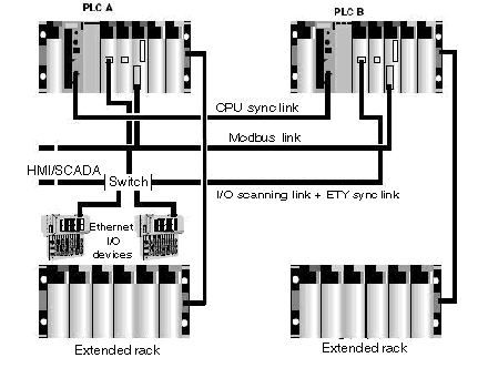
The following configuration is:
The link between the two monitored ETY modules, the ETY sync link cable, transfers information to diagnose the Hot Standby system and manages Ethernet I/O devices and/or other PLCs by configuring Ethernet I/O Scanning and/or Global Data in each monitored ETY.
You can use either of the following architectures:
-
a low-level architecture, which comprises two Ethernet switches connected together and each ETY connected to one of the switches
-
a high-level architecture, where several Ethernet ring switches are connected to the Ethernet devices and/or PLCs
For using hubs or switches in different network topologies, such as star, tree, or ring topologies, refer to the ConneXium catalog and the Transparent Ready User Guide.