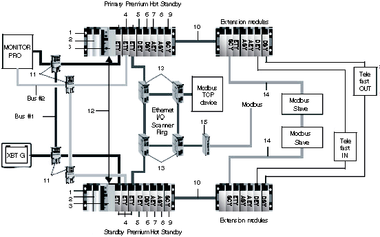
Hot standby systems deliver high availability through redundancy. They are used when downtime can not be tolerated. A Hot Standby PLC system may consist of a single rack configuration.
Components in a Hot Standby System
The mandatory redundant component requirements per rack are:
The optional redundant components are:
-
a TSX REY 200 Bus X remote rack master module
-
other TSX ETY 4103/5103 TCP/IP Ethernet communication modules (minimum firmware version 4.0)
-
Modbus communication module TSX SCP 114 in TSX SCY 21601
-
discrete/analog input modules
-
discrete/analog output modules
The two Hot Standby PLCs are configured with identical hardware and software. One of the Hot Standby processor TSX H57 24M or TSX H57 44M’s acts as the primary PLC, and the other acts as the standby PLC.
The CPU sync link is a point-to-point cable dedicated to application data exchange from the primary PLC to the standby PLC and to Hot Standby system diagnostics. Do not connect any other Ethernet devices on this link.
An ETY sync link cable runs between the two monitored ETY modules. A monitored ETY is used to diagnose the hot standby configuration and the communication between ETYs over the ETY sync link cable.
The Primary and Standby PLCs
The primary PLC:
-
executes the full application program
-
controls the Ethernet I/O and in-rack I/O
-
updates the standby PLC after every scan (program cycle); if the primary PLC fails, the standby PLC takes control within one scan.
The standby PLC:
-
executes only the first section of the full application program
-
checks the health of the primary PLC
-
does not control the in-rack or Ethernet I/O
NOTE:
The primary and the standby PLCs can manage local in-rack I/O with some restrictions.
At any moment, either of the two PLCs may be the primary or standby PLC—primary and standby states are interchangeable.
Switchover can only occur if one of the two PLCs is functioning as the primary PLC and the other one is in standby mode.
The Ethernet I/O and the redundant in-rack I/O are always controlled by the primary PLC.
1
Main rack with line terminator
2
Power supply
3
PLC processor (TSX H57 24M or TSX H57 44M)
4
Ethernet modules (TSX ETY 4103/5103, minimum firmware version 4.0) with monitored ETY managing an I/O scanner ring
5
Discrete input module (i.e. TSX DEY 64D2K)
6
Discrete output module (i.e. TSX DSY 64T2K)
7
Analog input module (i.e. low level isolated inputs, thermocouples, temperature probes, TSX AEY 414)
8
Analog output module (i.e. isolated output, TSZ ASY 410)
9
Communication module (TSX SCY 21601 with Modbus PCMCIA TSX SCP 114))
10
Bus X
11
Ethernet switch
12
CPU sync-link
13
Ethernet ring switch
14
Modbus RS485 cable
15
Modbus gateway (i.e. TSX ETG 1000)
A Modbus TCP device can be any of the following:
-
STB
-
OTB
-
Momentum I/O
-
ATV61
-
XBT G
-
XBT GT
-
Premium
A Modbus slave device can be any of the following:
