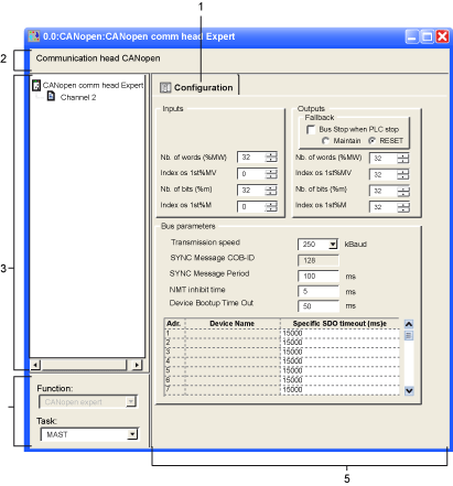
CANopen Master Configuration Screen with CPUs 20102/ 20302
(Original Document)
At a Glance
This screen is used to declare and configure the master of the CANopen network from a Modicon M340 PLC station.
Illustration
The configuration screen of the master is as follows:
Elements and functions
The table below describes the different areas which make up the master configuration screen:
Read
Number
Function
1
Tab
The tab in the foreground indicates the type of screen displayed. In this case, it is the configuration screen.
2
Module
This area is made up of the abbreviated heading of the processor equipped with a CANopen port.
3
Channel
This zone allows you to select the communication channel to be configured.
By clicking on the device, you display the tabs:
  • Description : gives the characteristics of the built-in CANopen port,
  • Inputs/outputs objects: allows pre-symbolizing of the input/output objects,
By clicking on a channel, you display the tabs:
  • Config . enables you to declare and configure the CANopen master,
  • Debug : accessible in online mode only,
  • Fault: accessible in online mode only.
4
General parameters
This field enables you to:
  • associate the CANopen bus to an application task:
    • MAST which is the master task,
    • FAST which is the rapid task.
The tasks are asynchronous in relation to exchanges on the bus.
5
Configuration
This field enables you to:
  • configure the PLC internal memory addresses where inputs from the CANopen devices will periodically be copied.
  • configure the PLC internal memory addresses where outputs from the CANopen devices will periodically be read.
  • configure the parameters of the CANopen bus.