The configuration screen allows configuration of the bus parameters as well as the inputs and outputs.
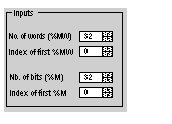
The figure below illustrates the inputs configuration area:
To configure the inputs of the bus slaves, it is necessary to indicate the memory areas to which they will be periodically recopied. To define this zone, you must indicate:
-
a number of words (%MW): from 0 to 32,464,
-
the address of the first word: from 0 to 32,463,
-
the number of bits (%M): from 0 to 32,634,
-
the address of the first bit: from 0 to 32,633.
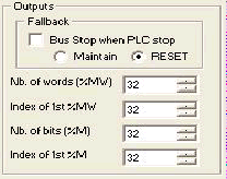
The figure below illustrates the outputs configuration area:
NOTE: The checkbox Bus Stop when PLC stop in the fallback area configuration is only available in CANopen expert mode.
-
If it is not checked: the CANopen bus remains in RUN after a PLC stop and the global strategy of fallback is applied to the outputs according to Maintain or Reset radio button.
-
If it is checked: the CANopen bus is stopped when a PLC stop; in this case, Maintain and Reset radio buttons are greyed out.
The fallback information area contains two radio buttons as well, which defines the behaviour of the device when the CPU is in STOP or in HALT:
To configure the outputs, it is necessary to indicate, as for the inputs, the word and bits tables that will contain the values of the bus slave outputs:
-
A number of words (%MW): from 1 to 32,464
-
The address of the first word: from 0 to 32,463
-
The number of bits (%M): from 1 to 32,634
-
The address of the first bit: from 0 to 32,633
NOTE: The word tables and bit tables are found in the PLC internal memory. Any crossover between two areas of each table is prohibited. The bits area for the inputs cannot overlap the bits area for the outputs. The words area for the inputs cannot overlap the words area for the outputs.
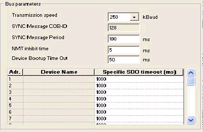
The figure below illustrates the bus parameters configuration area:
To configure the bus, it is necessary to indicate:
-
-
the of the synchronization message: 128 default,
-
the synchronization message period: 100 ms default.
-
the NMT inhibit time: 5 ms default. During Bootup, the CANopen Master implements a delay between each NMT messages to avoid slave overload. The value must be given in multiple of 100 μs. The value 0 disables the inhibit time.
-
the Device Bootup Time Out: 50 ms default. The global SDO timeout for the master is related to the scanning of the network. During this time, the master reads the object 1000 of each slave to analyze the CANopen bus configuration.
-
the Specific SDO timeout: 15000 ms default. The slaves SDO timeout is necessary for devices with long response times i.e. for accesses to the objects 1010,1011,1F50. A grid displays all present devices with the NodeId, the name and the timeout value.
The parameters presented below are represented in the %KW language objects:
|
Read
|
Parameter
|
Language object
|
|
Inputs
|
Number of words %MW
|
%KW8
|
|
Index of the first word
|
%KW10
|
|
Number of bits %M
|
%KW4
|
|
Index of the first bit
|
%KW6
|
|
Outputs
|
Fallback mode
|
%KW0
Least Significant Byte : 16#00,
Bit 2 to 7= 0, and :
-
Bit 0= 0 and Bit 1= 0: reset of outputs if task in STOP or HALT
-
Bit 0= 1 and Bit 1= 0: maintain of outputs if task in STOP or HALT
-
Bit 0= 0 and Bit 1= 1: bus in STOP if task in STOP or HALT
|
|
Number of words %MW
|
%KW9
|
|
Index of the first word
|
%KW11
|
|
Number of bits %M
|
%KW5
|
|
Index of the first bit
|
%KW7
|
|
Bus parameters
|
Transmission speed
|
%KW1
|
|
SYNC message COB-ID
|
%KW2
|
|
SYNC message period
|
%KW3
|


 WARNING