|
|
(Original Document)
|


|
Family
|
Element
|
Values
|
Meaning
|
|---|---|---|---|
|
Symbol
|
%
|
-
|
Indicates an IEC object.
|
|
Object type
|
I
|
-
|
Input object.
|
|
Q
|
-
|
Output object.
|
|
|
Format (size)
|
X
|
8 bits (Ebool)
|
Ebool type Boolean
(not compulsory).
|
|
W
|
16 bits
|
16 bit WORD-type word.
|
|
|
D
|
32 Bit
|
32 bit DINT-type word.
|
|
|
F
|
32 Bit
|
32 bit REAL-type word.
|
|
|
Module/channel address and connection point
|
b
|
3 to 999
|
Bus number.
|
|
e
|
1 to 63
|
Connection point number (CANopen slave number).
|
|
|
Rack number
|
r
|
0
|
Virtual rack number, always 0.
|
|
Module number
|
m
|
0
|
Virtual module number, always 0.
|
|
Channel number
|
c
|
Equal to 0 for all devices except the FTBs (channels numbered 0 to 7, then from 10 to 17).
|
Channel number.
|
|
Rank of data in the channel
|
d
|
0...999
|
Data number of slave.
This number can vary from 0 to 999 because a slave can only have a maximum of 1000 input and output words.
|
|
Module digital/TOR autonomous with Boolean vision
|
|
|
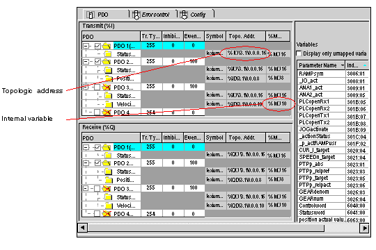
%I\3.4\0.0.5
|
Boolean value is entered on channel 5
(rang 0 omitted).
|
|
Module digital standard
|
|
|
%IW\3.4\0.0.0.2.5
|
Boolean value is entered on unique channel 0, rank 2, bit 5.
The mapping is given when the DCF file is imported.
|
|
Digital module on an Advantys STB island
|
|
|
%IW\3.4\0.0.0.3.2
|
Word 3, bit 2, data by Advantys Configuration Software.
|
|
Type of data
|
Topologic address:
|
|
|
2 input words
|
%IW \3.4\0.0.0.0 or %IW \3.4\0.0.0.1
|
|
|
1 double input word
|
%ID \3.4\0.0.0.2
|
|
|
1 floating input
|
%IF \3.4\0.0.0.4
|
|
|
1 output word
|
%QW\3.4\0.0.0.6
|
|
