Hardware Configuration of the Bus
(Original Document)
At a Glance
Once the hardware configuration for the slaves and CANopen master has been completed, you must now connect these different devices.
Wiring Examples for the Bus
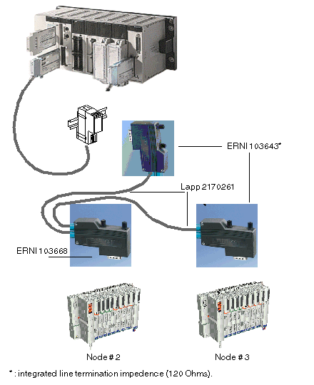
The figure below represents a wiring solution.
Some References
Wire example from the Selectron company:
For additional information, see the Internet site: http://www.selectron.ch.
Wire example from the Lapp company:
For additional information, see the Internet site: http://www.lappcable.com/products.
Example of connectors from the ERNI company:
For additional information, see the Internet site: http://www.erni.com.
Connector Diagram
The connectors used are 9-pin SUB D connectors:
Description of the Pins
This table provides the function of each pin.
Element
Description
1
Reserved
2
CAN_L
3
CAN_GND
4
Reserved
5
NC
6
NC
7
CAN_H
8
Reserved
9
NC
NOTE: Make sure that you correctly connect the cable shielding to the connector.
For more details, consult the CANopen Hardware Setup Manual available on telemacanique.com.