|
Examples of function block SERVO
|
|
|
Original instructions
|
|
Parameter
|
Specification
|
|---|---|
|
t_motor
|
25 s
|
|
t_mini
|
1 s
|
|
sampling period
|
4 s
|
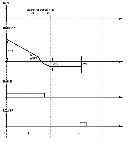
|
Position No.
|
Explanation
|
|---|---|
|
1
|
The variance IN-RCPY is 20%: a pulse of length 5 s (=20% of 25 s) was generated at the RAISE output.
|
|
2
|
The variance is still only 10%, a pulse of 2.5 s (= 10% of 25 s) was generated at the RAISE output; the second left over from the previous pulse is not taken into account.
|
|
3
|
The deviation now amounts to -2%, which corresponds to a pulse of 0.5 s on LOWER. Since t_mini is 1 s, no pulse is generated (the duration of 0.5 s is saved however).
|
|
4
|
The variance is still -2%, but the corresponding pulse (0.5 s) is added to the previously stored pulse to make 1 s. The length corresponds to t_mini, so the pulse is locked onto the LOWER output.
|
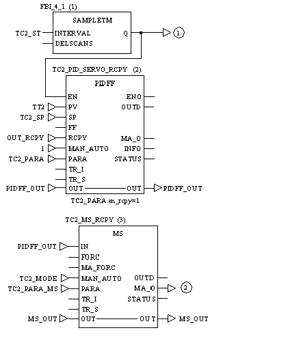
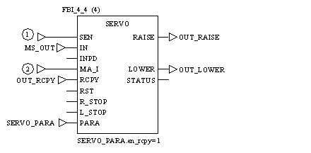
OUT_RCPYProcess value of the valve positional feedback
|
Parameter
|
Specification
|
|---|---|
|
t_motor
|
25 s
|
|
t_mini
|
1 s
|
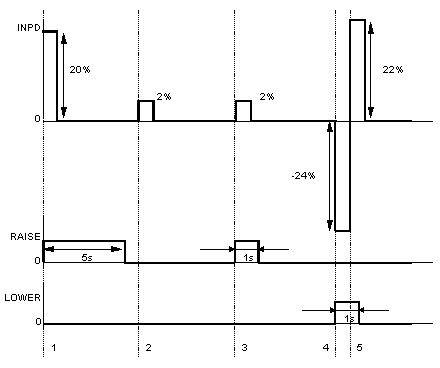
|
Position No.
|
Explanation
|
|---|---|
|
1
|
The modification of the PID control output is +20%, in this case the pulse affects the RAISE output and lasts 5 s (= 20% of 25 s).
|
|
2
|
The modification of the PID controller is +2% which corresponds to a pulse duration of 0.5 s. The pulse is less than t_mini (=1 s.) so it does not influence the outputs.
|
|
3
|
At the second modification of +2 %, the function adds this modification to the previous one (which corresponds to a variance which was below the minimum value), which corresponds to a positive total modification of +4 %, i.e. a pulse of 1 s at the RAISE output.
|
|
4
|
For a modification of -24 % the pulse at the LOWER output is 6 s
|
|
5
|
Before the end of the following second a further modification of + 22 % leads to a total system modification of 2 %< modification of t_mini (4 %). The function ends with the minimum pulse of 1 s.
|
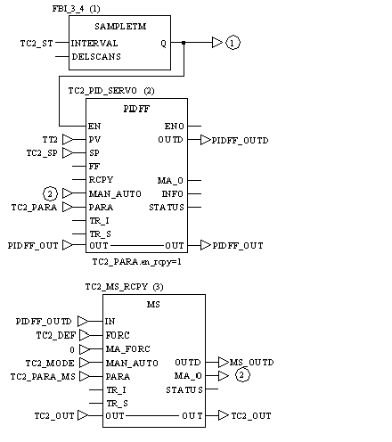
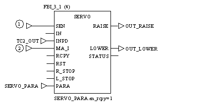

TC2_DEFFError output of the process value TC2: If TC2 is faulty, the servoloop is forced into manual mode.