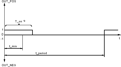
The period duration determines the time during which the actuating pulses (1-signals at the output OUT_POS or OUT_NEG) are output at regular intervals, i.e. within a constant time pattern.
The parameter
t_min specifies the minimum pulse length, i.e. the time span in which the output
OUT_POS or
OUT_NEG should carry a "1" signal. If the length of the pulse calculated according to the equation in section
Pulse length formulas for OUT_POS and OUT_NEG are smaller than
t_min, no pulse will be given for the entire period.
An overview of the ratios between times is shown in the following diagram:
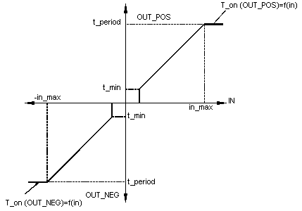
The parameter in_max marks the point of the input variable IN, for which the output OUT_POS would continuously carry "1" if the IN input variable is positive.
The dependency of the time duration in which the output OUT_POS (OUT_NEG) carries a 1-Signal, on the input variable IN is illustrated in the following diagram:
In reset mode RST = 1, the outputs OUT_POS and OUT_NEG are set to "0". The internal time counters are standardized as well so that the function block begins its transition to RST=0 with the output of a new 1-signal on the associated output.
If the PWM1 block is operated together with a PID controller, then the period t_period should be so selected, that it corresponds to the PID controllerís scan time. It is then guaranteed that every new actuating signal from the PID controller within the period time can be fully processed.
The PWM1 scan time should be selected according to how the pulse time compares to the period length. Though this, the smallest possible actuating pulse is be determined.
The following ratio is recommended:


