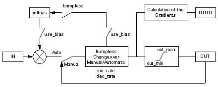
The following diagram displays the structure of the function block:
Setting of the mode selection
The mode selection can be set depending on input FORC either via the PLC program or via a server dialog (monitoring device):
|
Input FORC
|
Set the operating mode
|
|
0
|
Setting through the input MAN_AUTO (via operating device):
MAN_AUTO= 1: Automatic operating mode
MAN_AUTO= 0: Manual mode
In this case the input MA_FORC is ineffective.
|
|
1
|
Setting through the input MA_FORC (via PLC program):
MA_FORC = 1: Automatic operating mode
MA_FORC = 0: Manual mode
In this case the input MA_AUTO is ineffective.
|
The output MA_O always indicates the current operating mode of the function block.
Characteristics of the output
OUT
The following characteristics apply to the output OUT:
-
Automatic mode: The output OUT is a copy of the input IN.
In this operating mode, the output OUT can be assigned an OUTBIAS value (use _bias to 1). OUT calculates as follows: OUT = IN + outbias.
-
Manual mode: The function block does not set the output, the server can directly change the value that is the connected variable at the output OUT.
-
The output OUT is principally limited to an area between out_min and out_max . When the value calculated by the function block (or entered by the server in manual mode) exceeds one of these limit values, the value of OUT will be cut (to out_min or out_max).). The incremental output OUTD on the other hand, does not take this cut into consideration.
Switch between manual and automatic
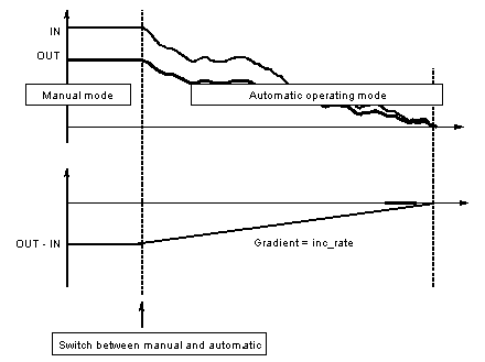
The switch manual/automatic at output appears bumpless, as the value of IN is not suddenly led to the output.
The output OUT gets closer to input IN ramps with positive (inc_rate) or negative increase (dec_rate):
bumpless changeover
The bumpless changeover can be annulled with the increasing ramp, when inc_rate is set to 0. Just as with dec_rate = 0 the changeover is with decreasing ramp with bumps. In both cases the input IN will travel immediately to output OUT when changed over to automatic mode.
When the parameter Outbias (use_bias = 1) is used, a bumpless manual/automatic changeover can be achieved without change of the output, when the bumpless parameter is set to 1. In this case the parameter Outbias will be newly calculated and the deviation between the input IN and the output OUT will be considered.
Bumpless changeover with the parameter Outbias
The bumpless changeover manual/automatic is advisable when the input of the function block is not connected to any controller or to a controller output without integral component.


