Parameter assignment for the function block is accomplished by specifying the integration GAIN and the limiting values OUT_MAX and OUT_MIN for the output OUT.
The limits OUT_MAX and OUT_MIN limit the upper output as well as the lower output. Hence OUT_MIN ≤ OUT ≤ OUT_MAX.
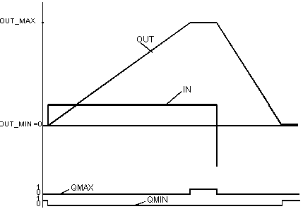
The outputs QMAX and QMIN show that the output has reached a limit or the output signal has been capped.
There are two operating mode selectable through the TR_S parameter input.
|
Operating mode
|
TR_S
|
Meaning
|
|
Automatic
|
0
|
The Function block will be handled as " Parametering" describes. |
|
Tracking
|
1
|
The tracking value TR_I is transferred directly to the output OUT. The control output is, however, limited by OUT_MAX and OUT_MIN.
|
The input signal is integrated via the time. In the event of a transition at the input IN, the output will rise (if the IN values are positive) or fall off (if the IN values are negative) along a ramp function. OUT will always be between OUTMAX and OUT_MIN; if OUT is equal to OUT_MAX or OUT_MIN, it will be so indicated in QMAX or QMIN.
Representation of the integrator step response:
