The following bits of the diagnostic word (diag element) show the status of the autotuning:
|
Bit
|
Meaning
|
|
|
1 = Initial non-stabilized measurement
|
|
|
1 = Length of actuating pulse (tmax) too short
|
|
|
1 = Too much noise/interference
|
|
|
1 = Length of actuating pulse (tmax) too long
|
|
|
1 = Measured value has been significantly exceeded
|
|
|
1 = Process without minimum phase
|
|
|
1 = Asymmetrical Process
|
|
|
1 = Integrating Process
|
Bit 9 of the
diag element
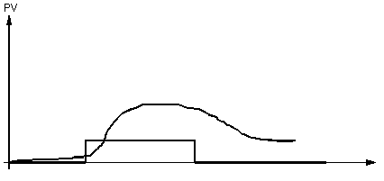
This image illustrates behavior when measurements are not initially stabilized:
The automatic regulator setting was implemented, although the measurement was not stable. If the measured change is large relative to the reaction of the actuating pulse, then the test results will be distorted.
Bit 10 of the
diag element
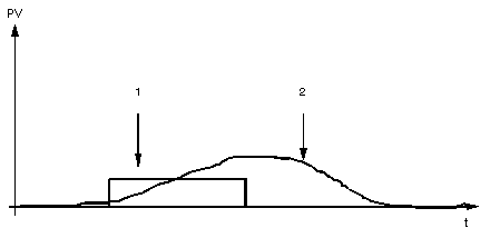
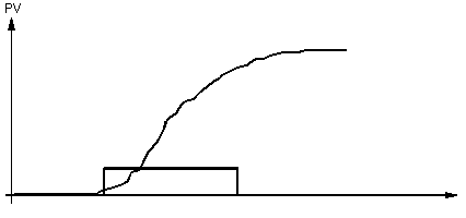
This image illustrates behavior when the actuating pulse is too short:
1
Actuating pulse test
2
Process reaction
The reaction will not be stabilized before returning to the original manipulated variable. The calculated parameters are therefore false.
Bit 11 of the
diag element
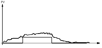
This image illustrates the behavior when noise/interference is too high:
The reaction of the process to the actuating pulse is insufficient relative to the level of noise/interference. The measurement should be filtered or step_ampl should be increased.
Bit 12 of the
diag element
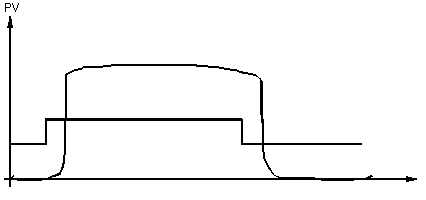
This image illustrates behavior when the actuating pulse is too long:
tmax specifies the frequency with which the measurement is taken, i.e. the value that is used to calculate the coefficients. tmax must be between 1 and 5 times the rise time of the repeated task.
Bit 13 of the
diag element
This bit is used when the reaction to an actuating pulse significantly exceeds (overshoots) the measured value (i.e. by more than 10%). The process does not conform to the models used by the algorithms.
Bit 14 of the
diag element
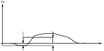
This bit is used when the reaction to an actuating pulse leads to inversion of the reaction at the initial stage (i.e. undershoots by more than 10%). The process does not conform to the models used by the algorithms.
Bit 15 of the
diag element
This image illustrates the behavior when the process is asymmetrical.
The reaction of the process is asymmetrical.
The last parameter set must be a compromise between the reactions at ascent and descent. Both cases concern average performance.
If the desired criterion is the length of the reaction on ascent, then the first parameter set must be taken into consideration. During the return phase (to the original manipulated variable) the automatic regulator setting is turned off. If the desired criteria is the length of descent, then a negative amplitude must be used.
Bit 16 of the
diag element
This image illustrates the behavior during an integration process.
The process includes an integral component or tmax is too small and the process asymmetrical. The calculated coefficients must correlate to the process with the integral coefficient If this is not the case, the automatic regulator setting should be restarted, after tmax has been increased.
