|
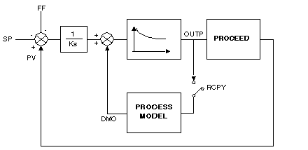
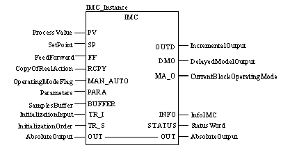
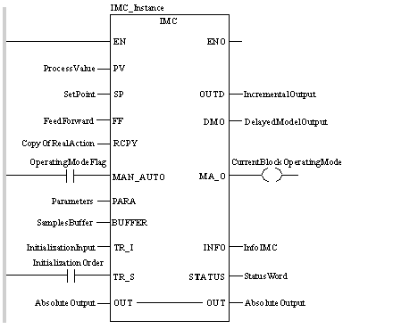
Description
|
|
|
Original instructions
|
 WARNING WARNING |
|
UNEXPECTED OUTPUT BEHAVIOUR
Make sure that the function block is always invoked in the first program cycle.
For a correct behaviour you must synchronize the model corrector with the SAMPLE_TM function and adjust the INTERVAL variable to the same value as T_ECH of IMC
Failure to follow these instructions can result in death, serious injury, or equipment damage.
|


CAL IMC_Instance(PV:=ProcessValue,SP:=SetPoint,
    FF:=FeedForward, RCPY:=CopyOfRealAction,
    MAN_AUTO:=OperatingModeFlag,PARA:=Parameters,
    BUFFER:=SamplesBuffer, TR_I:=InitializationInput,
    TR_S:=InitializationOrder, OUT:=AbsoluteOutput,
    OUTD=>IncrementalOutput,DMO=>DelayedModelOutput,
    MA_O=>CurrentBlockOperatingMode, INFO=>InfoIMC,
    STATUS=>StatusWord)
IMC_Instance (PV:=ProcessValue, SP:=SetPoint,
    FF:=FeedForward, RCPY:=CopyOfRealAction,
    MAN_AUTO:=OperatingModeFlag,PARA:=Parameters,
    BUFFER:=SamplesBuffer, TR_I:=InitializationInput,
    TR_S:=InitializationOrder, OUT:=AbsoluteOutput,
    OUTD=>IncrementalOutput,DMO=>DelayedModelOutput,
    MA_O=>CurrentBlockOperatingMode, INFO=>InfoIMC,
    STATUS=>StatusWord);
 CAUTION CAUTION |
|
UNEXPECTED BEHAVIOR OF APPLICATION
Do not set the datatype of the PARA input parameter to constant, in the general attributes tab of the Data Properties window.
Failure to follow these instructions can result in injury or equipment damage.
|
|
Parameter
|
Type
|
Meaning
|
|---|---|---|
|
PV
|
Measurement (Process Value)
|
|
|
SP
|
REAL
|
Set point
|
|
FF
|
REAL
|
Feed Forward input (FeedForward)
|
|
RCPY
|
REAL
|
External input of the model
|
|
MAN_AUTO
|
Operating mode of the corrector:
"1": automatic mode
"0": manual mode
|
|
|
PARA
|
Internal parameters
|
|
|
BUFFER
|
ARRAY [n..m] OF REAL
|
Floating point table containing the input value to be delayed.
|
|
TR_I
|
REAL
|
Initialization input (tracking)
|
|
TR_S
|
BOOL
|
Initialization command
|
|
Parameter
|
Type
|
Meaning
|
|---|---|---|
|
OUT
|
Analog output of the corrector
|
|
Parameter
|
Type
|
Meaning
|
|---|---|---|
|
OUTD
|
REAL
|
Differential output: difference between the current cycle output and that of the previous cycle
|
|
DMO
|
REAL
|
Module output, including delay.
|
|
MA_O
|
Current function block operating mode:
"1": automatic mode
"0": other mode (i.e. manual or tracking)
|
|
|
Info_IMC
|
REAL
|
Information
|
|
STATUS
|
Status word
|
|
Parameter
|
Type
|
Meaning
|
|---|---|---|
|
KS (1)
|
Static gain of the process in open loop
Default value: 1.0, limits: 0.0/3E38.
|
|
|
OL_TIME(1)
|
REAL
|
Time constant of the process in open loop
Default value: 1.0, limits: 0.0/3E38.
|
|
CL_PERF
|
REAL
|
Relationship of the natural time constants (open loop)/required (closed loop)
Default value: 1.0, limits: 0.0/3E38.
|
|
T_DELAY
|
REAL
|
Current pure delay time.
Default value: 0.0, limits: 0.0/3E38.
Note: If this value is not a whole sampling period multiple, then it is automatically replaced by the whole sampling period multiple which is immediately below.
|
|
DBAND
|
REAL
|
Dead band around the deviation.
Default value: 0, limits: 0.0/3E38.
|
|
T_ECH
|
REAL
|
Sampling period.
Default value: 0,3, limits: 0.0/3E38.
|
|
REV_DIR
|
Direction of action:
"1": direct action
"0": reverse action
|
|
|
En_rcpy
|
BOOL
|
"1"= RCPY used (initial value = 0)
|
|
Id
|
Reserved for the automatic control of the controller.
|
|
|
PV_INF
|
REAL
|
Low scale of PV PV (default value: 0.0)
|
|
PV_SUP
|
REAL
|
High scale of PV PV (default value: 100.0)
|
|
OUT_INF
|
REAL
|
Low scale of output OUT (default value: 0.0)
|
|
OUT_SUP
|
REAL
|
High scale of output OUT (default value: 100.0)
|
|
OUT_MIN
|
REAL
|
Low limit of output OUT (default value: 0.0)
|
|
OUT_MAX
|
REAL
|
High limit of output OUT (default value: 100.0)
|
|
OUTRATE
|
REAL
|
Velocity limit OUT (default value: 0.0)
|
|
FF_INF
|
REAL
|
Low scale of Feedforward input (default value: 0.0)
|
|
FF_SUP
|
REAL
|
High scale of Feedforward input (default value: 100.0)
|
|
OTFF_INF
|
REAL
|
Low limit of Feedforward input (default value: 0.0)
|
|
OTFF_SUP
|
REAL
|
High limit of Feedforward input (default value: 100.0)
|
|
DEV
|
REAL
|
PV-PS deviation
|
|
OUT_FF
|
REAL
|
Output value of the FF action
|
|
Base
|
Lower limit
|
Upper limit
|
|---|---|---|
|
Hexadecimal
|
16#0
|
16#FFFF
|
|
Octal
|
8#0
|
8#177777
|
|
Binary
|
2#0
|
2#1111111111111111
|
|
Data
|
Representation in one of the bases
|
|---|---|
|
0000000011010011
|
16#D3
|
|
1010101010101010
|
8#125252
|
|
0000000011010011
|
2#11010011
|
