Connecting 28-pin Terminal Block
Original instructions
Overview
The module uses one of the 2 types of 28-pin removable terminal blocks:
Cable Ends and Contacts
Each terminal block can accommodate:
28-pin Terminal Blocks Description
The following table describes the characteristics of the terminal blocks:
-
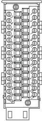
BMXFTB2800 Caged Clamp Terminal Block
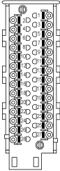
BMXFTB2820 Spring Terminal Block
Front view
Number of wires supported
1
1
Wire gauge supported
Minimum
AWG 24 (0.34 mm2)
Maximum
AWG 16 (1.5 mm2)
Wiring constraints
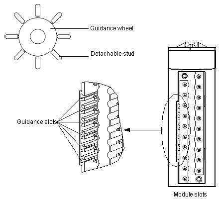
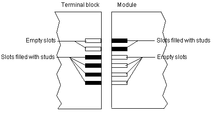
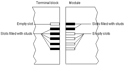
Caged clamp terminal blocks have captive screws. On the supplied blocks, these screws are not tightened.
To tighten the screws, use flat-tipped screwdriver with a diameter of 3 mm.
To insert and remove wires from the connectors, use a 2.5 x 0.4 mm screwdriver to open the clamp by pushing the corresponding button.
Maximum screw tightening torque
0.5 N•m (0.37 lb-ft)
The connectors of the terminal blocks are designed for only one wire or one cable end.
DANGER
LOOSE WIRING CAUSES ELECTRIC SHOCK
Do not connect more than one wire per terminal block connector.
Failure to follow these instructions will result in death or serious injury.
Installing the 28-Pin Terminal Block
DANGER
HAZARD OF ELECTRIC SHOCK, EXPLOSION OR ARC FLASH
  • Ensure that the turbomachinery is stopped while connecting or disconnecting the module or the terminal block.
  • Connect or disconnect the terminal block with sensor and pre-actuator voltage switched off.
Failure to follow these instructions will result in death or serious injury.
Plugging a terminal block into the incorrect electronic module can cause an electric shock or unintended operation of the application and/or damage the electronic module.
Coding the terminal block help to prevent the terminal block from being mounted on an incorrect module.
DANGER
ELECTRIC SHOCK OR UNINTENDED EQUIPMENT OPERATION
Connect the terminal blocks to their designated location.
Failure to follow these instructions will result in death or serious injury.
CAUTION
TERMINAL BLOCK IMPROPERLY FIXED TO THE MODULE
  • Follow the procedure instructions to fix the terminal block to the module.
  • Verify that the screws are tightened.
Failure to follow these instructions can result in injury or equipment damage.
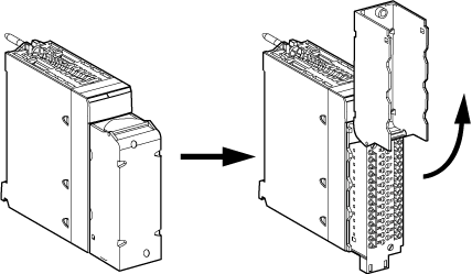
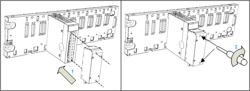
To fit the 28-pin terminal block onto the module, follow these steps:
Step
Action
1
Insert the rear lower part of the terminal block into the front lower part of the module.
2
Tighten the two mounting screws located on the lower and upper parts of the terminal block.
NOTE: Apply a tightening torque of 0.4 N•m (0.30 lb-ft).
The following figure shows the method for opening the 28-pin terminal block cover so that it can be wired.
Labeling 28-Pin Terminal Block
The label for the 28-pin terminal block is supplied with the module.
Each label has two sides and can be slitted behind the front part of the cover:
Coding the Terminal Block
When installing a terminal block on a module, you can code the terminal block so that it may be used only with a particular module. To do this, apply studs to both the terminal block and to the module in a pattern so that the 2 components fit each other, but do not fit other modules or terminal blocks. In this way, you can reduce the likelihood that a terminal block will be mounted on a module other than the intended module.
To perform coding, use the studs on the STBXMP7800 guidance wheel. You can insert studs in the 6 guidance slots on the left side of the module, and in the corresponding 6 slots in the terminal block.
NOTE: The module connector has indicators that show the proper direction for inserting studs into a terminal block installation.
To fit the terminal block to the module:
The following diagram depicts a guidance wheel and the slots on the module used for coding the terminal block:
The following example depicts a coding configuration that allows a terminal block to fit together with a module:
The following example depicts a coding configuration that obstructs the terminal block from fitting onto the module: