|
|
Original instructions
|
 WARNING WARNING |
|
UNINTENDED EQUIPMENT OPERATION
Do not operate this equipment outside of its specified temperature range.
Failure to follow these instructions can result in death, serious injury, or equipment damage.
|
|
Module Reference
|
Range
|
|---|---|
|
BMECXM0100
|
0...60 ºC (32...140 ºF)
|
|
BMECXM0100H
|
-25...70 ºC (-13...158 ºF)
|
|
Characteristics
|
Description
|
|
|---|---|---|
|
Protocol supported
|
CANopen
|
|
|
Connection type
|
Sub-D 9, male
|
|
|
Standard
|
CANopen CiA 301 V4.2
|
|
|
Maximum cable length
|
Refer to chapter Transmission Speed and Cable Length.
|
|
|
Isolation between CAN bus and ground
|
500 Vac RMS, 700 Vdc
|
|
|
CAN bus transmission baud rate (kbd)
|
20, 50, 125, 250, 500, 1000
|
|
|
CANopen slave devices supported
|
63 maximum
|
|
|
Services
|
NMT
|
NMT master according to DS 301
|
|
Boot-up procedure according to DS 302
|
||
|
SDO
|
1 SDO client
1 SDO server
|
|
|
PDO
|
256 PDOs IN and 256 PDOs OUT
|
|
|
SYNC
|
Producer
|
|
|
Emergency message
|
Consumer only
|
|
|
Health
|
Heartbeat
|
|
|
Node Guarding
|
||

|
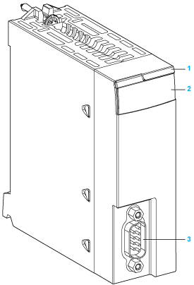
Number
|
Element
|
Function
|
|---|---|---|
|
1
|
Module name
|
BMECXM0100 or BMECXM0100H
|
|
2
|
LED array
|
Observe the LED display to diagnose the module.
|
|
3
|
SUB-D 9 connector
|
CANopen port
|
|
LED
|
Color
|
Description
|
|---|---|---|
|
RUN
|
Green
|
Indicates module operating status.
|
|
ERR
|
Red
|
Detected error in module operation.
|
|
I/O
|
Red
|
Indicate exchange status with CANopen devices.
|
|
BS (Bus Status)
|
Red / green
|
Indicates the EtherNet/IP connection status.
|
|
Yellow
|
Firmware upgrade in progress
|
|
|
CAN RUN
|
Green
|
Indicates the status of the CANopen fieldbus.
|
|
CAN ERR
|
Red
|
Indicates the status of the CANopen physical layer and indicates detected errors due to missing CAN messages (SYNC, node-guarding or heartbeat)
|
|
CAN COM
|
Yellow
|
Dedicated to SDO transmission
|

|
Pin
|
Signal
|
Description
|
|---|---|---|
|
1
|
–
|
Reserved
|
|
2
|
CAN_L
|
CAN_L bus line (Low)
|
|
3
|
CAN_GND
|
CAN ground
|
|
4
|
–
|
Reserved
|
|
5
|
CAN_SHLD
|
CAN shield
|
|
6
|
CAN_GND
|
CAN ground
|
|
7
|
CAN_H
|
CAN_H bus line (High)
|
|
8
|
–
|
Reserved
|
|
9
|
Reserved
|
CAN external power supply that is dedicated to the optocouplers power and transmitters-receivers (optional).
|