Connections
(Original Document)
AS-i Bus Cables
AS-i bus cables carry the signals and supply the sensors and actuators connected to the bus with 30 Vdc.
Types of AS-i cables:
Cable type
Specifications
Illustration
Polarized AS-i ribbon cable
Color: yellow. Wire cross-section: 1.5 mm2
Standard round cable
Wire cross-section: 1.5 mm2 or 2.5 mm2
Recommended cable: Product reference H05VV-F2x1.5, conforms to the DIN VDE 0281 standard. Wire cross-section: 1.5 mm2.
Cable Routing
The AS-i cable and the power cables carrying higher power levels must be in separate ducts, which are protected by a metal screen.
When using a shared route for control cables it is essential that the connections on these control links should conform to the technology rules (e.g. the discharge diode or limiters on the terminals of self-inductive elements etc.).
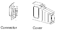
Connector
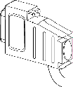
A set (connector + cover) is delivered with the module, which is used to connect the module to the AS-i bus. This connector must be linked to the cable of the AS‐i bus and assembled by the user according to the procedure described later.
Illustration:
Connection of Module to Bus
To connect a module to the bus, follow the procedure below:
Step
Action
1
Connect the 2 wires of the AS-i cable to the connector, taking the polarities into account:
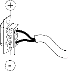
In the special event that a shielded cable is used, this should be connected to the central terminal.
2
Mount the connector in its cover and fix the cable to it:
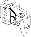
3
Click the cover shut:
4
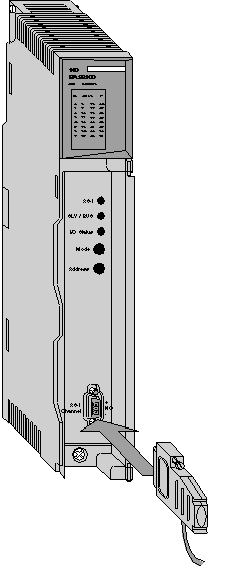
Mount the assembled unit on the module: