|
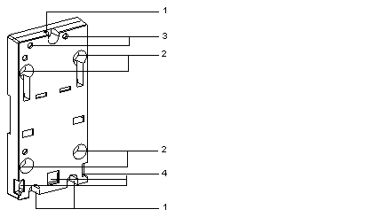
Physical description of the support board
|
|
|
(Original Document)
|

|
Numbers
|
Description
|
|---|---|
|
1
|
Three 5.5mm diameter holes enabling the support board to be fixed to a panel or to an AM1-PA perforated mounting plate with a mounting distance of 140mm (the standard mounting distance for Micro PLCs).
|
|
2
|
Four 6.5mm diameter holes enabling the support board to be fixed to a panel or to an AM1-PA perforated mounting plate with a mounting distance of 88.9mm (the standard mounting distance for Premium PLCs).
|
|
3
|
Two M4 screws enabling the TSX SUP A02 power supply to be fixed in place.
|
|
4
|
Slots for fixing the pins situated at the bottom and to the rear of the module.
|