|
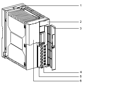
Physical description of the TSX SUP A02 power supply module
|
|
|
(Original Document)
|

|
Numbers
|
Description
|
|---|---|
|
1
|
Support board enabling the power supply module to be fitted directly onto an AM1-DE200/DP200 type DIN rail or to a Telequick AM1-PA mounting plate
|
|
2
|
Display panel comprising:
|
|
3
|
Protective flap for terminal block.
|
|
4
|
Screw terminal block for connection:
|
|
5
|
Hole for threading of cable tie.
|
|
6
|
110/220 V voltage selector switch. On delivery, the selector is set at 220V.
|