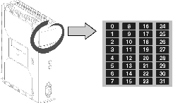
The module display panel displays the presence and operating status of each slave on the AS-i bus.
Illustration:
Diagnostics of the AS-i Bus
Table giving diagnostics of module's standard and extended address setting slaves:
View of standard or extended address setting slaves on bank A:
/B LED off
|
View of extended address setting slaves on bank B:
/B LED on
|
View of AS-i bus image. Each LED from 1 to 31 corresponds to a standard or extended slave address on the bus.
-
LED on: slave active
-
LED off: slave not expected and not detected.
-
LED flashes rapidly: peripheral fault on slave.
-
LED flashing slowly: configuration fault on slave.
|
View of AS-i bus image. Each LED 1 to 31 corresponds to an extended address setting slave address on the bus.
-
LED on: slave present
-
LED off: slave not expected and not detected.
-
LED flashes rapidly: peripheral fault on slave.
-
LED flashing slowly: configuration fault on slave.
|
Diagnostics example with 5 slaves addressed at 1, 4, 10, 11, 20:
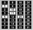
In brief :
-
LEDs for slaves 1, 4, 10, 20 are lit, therefore these slaves are active,
-
slave 11's LED is flashing, so it is faulty,
-
the other LEDs are off because no slaves are expected or detected at these addresses.
|