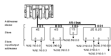
Addressing of language objects associated with the slave devices connected to the AS-i bus
(Original Document)
At a glance
Acquisition of inputs and update of slave device outputs connected to the AS-i bus are carried out automatically. This occurs at the start and end of each cycle respectively of the task in which the TSX SAY 100 module is configured.
The user program has access to these inputs and outputs via the language objects.
Addressing is defined in the following way:
Syntax
The table below describes the different elements that make up addressing.
Family
Item
Values
Indicates
Symbol
%
-
-
Object type
I
Q
-
-
Picture of the physical input of the module,
Picture of the physical output of the module,
This information is exchanged automatically each cycle of the task to which they are attached.
Bus and slave No.
b
1 to 999
Bus number.
Except the value 2 if Fipio is used.
e
1 to 31
Slave Number
Rack number
r
0
Virtual rack number.
Module position
m
0
Virtual module position
Channel
c
0 to 3
Input or output number
Example
%I\4.1\0.0.3 indicates: input 3 of bus number 4 of slave 1 and implicitly rack 0 and module 0 of the TSX SAY 100 module.
%Q\8.31\0.0.0 indicates: output 0 of bus number 8 of slave 31 and implicitly rack 0 and module 0 of the TSX SAY 100 module.
Illustration:
NOTE: The physical address of an AS-i slave is programmed by a console.
Multiple Address Settings
When one or more slaves are connected, make sure that you do not assign an address which is already being used by a slave on the bus.
If slave address is doubled then two scenarios may occur  :