|
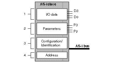
Structure of an AS-i slave
|
|
|
(Original Document)
|

|
Number
|
Item
|
Description
|
|---|---|---|
|
1
|
Input/output data
|
Input data is stored by the slave and made available for the AS-i master.
Output data is updated by the master module.
|
|
2
|
Parameters
|
The parameters are used to control and switch internal operating modes to the sensor or the actuator.
|
|
3
|
Configuration/Identification
|
This field contains:
|
|
4
|
Address
|
Physical address of slave.
|
|
Note: The operating parameters, address, configuration and identification data are saved in a non-volatile memory.
|
||