This DFB enables monitoring the AS-Interface bus for detected errors on:
-
Module and bus itself
-
Missing slave
-
Non-configured slave
-
Slave
This DFB must be in an application to display detailed diagnostic information in the diagnostic viewer.
For a description of how the ASI_DIA DFB works, go
here.
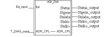
Representation:
ASI_DIA instance name: ASI_1
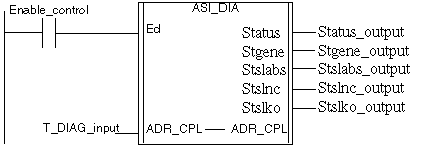
Representation:
ASI_DIA instance name: ASI_1
Representation:
Cal ASI_1(Ed:=Enable_control, ADR_CPL:=T_DIAG_input, Status=>Status_output, Stgene=>Stegene_ouput, Stslabs=>Stslabs_ouput, Stslnc=>Stslnc_output, Stslko=>Stslko_output)
Representation:
ASI_1(Ed:=Enable_control, ADR_CPL:=T DIAG_input, Status=>Status_output, Stgene=>Stegene_ouput, Stslabs=>Stslabs_ouput, Stslnc=>Stslnc_output, Stslko=>Stslko_output);
Description of the parameters
The following table describes the Input parameter:
|
Name
|
Type
|
Description
|
|
ED
|
EBOOL
|
DFB activation bit, if ED = 0, the AS-Interface bus is not monitored
|
The following table describes the Input/ Output parameter:
|
Name
|
Type
|
Description
|
|
ADR_CPL
|
T_COM_ASI_DIAG
|
Address of the AS-Interface Master Channel (IODDT)
|
The following table describes the Output parameters:
|
Name
|
Type
|
Role
|
Description
|
|
STATUS
|
WORD
|
Error Type
|
The next bits indicate the type of detected error:
|
|
STGENE
|
WORD
|
Module or bus error
|
Detail of the detected module or bus error:
-
Bit 0 =1: The AS-Interface module does not give OK response to module identification request
-
Bit 1 = 1: Slave with 0 address detected on the AS-Interface bus
-
Bit 2 = 1: Detected AS-Interface Power supply error
-
Bit 3 = 1: OFFLINE phase active
-
Bit 4 = 1: DATA_EXCHANGE mode inactive
-
Bit 5 = 1: No slave presence on the bus
-
Bit 6 = 1: Detected peripheral error
|
|
STSLABS
|
ARRAY [0..3] of WORD
|
List of absent slaves
|
Default values = 0
STSLABS[0]: slaves 0A to 15A:
-
Bit 0: Not significant, always set to 0
-
Bit 1 = 1: The configured slave at address 1A is absent, [...]
-
Bit 15 = 1: The configured slave at address 15A is absent
STSLABS[1]: slaves 16A to 31A:
-
Bit 0 = 1: The configured slave at address 16A is absent, [...]
-
Bit 15 = 1:The configured slave at address 31A is absent
STSLABS[2]: slaves 0B to 15B:
-
Bit 0: Not significant, always set to 0
-
Bit 1 = 1: The configured slave at address 1B is absent, [...]
-
Bit 15 = 1 The configured slave at address 15B is absent
STSLABS[3]: slaves 16B to 31B
-
Bit 0 = 1: The configured slave at address 16B is absent, [...]
-
Bit 15 = 1: The configured slave at address 31B is absent
|
|
STSLNC
|
ARRAY [0..3] of WORD
|
List of not configured slaves
|
Default values = 0
STSLNC[0]: slaves 0A to 15A:
-
Bit 0: Not significant, always set to 0
-
Bit 1 = 1: The detected slave at address 1A is not configured, [...]
-
Bit 15 = 1: The detected slave address 15A is not configured
STSLNC[1]: slaves 16A to 31A:
-
Bit 0 = 1: The detected slave at address 16A is not configured, [...]
-
Bit 15 = 1:The detected slave at address 31A is not configured
STSLNC[2]: slaves 0B to 15B
-
Bit 0: Not significant, always set to 0
-
Bit 1 = 1: The detected slave at address 1B is not configured, [...]
-
Bit 15 = 1 The detected slave at address 15B is not configured
STSLNC[3]: slaves 16B to 31B:
-
Bit 0 = 1: The detected slave at address 16B is not configured, [...]
-
Bit 15 = 1: The detected slave at address 31B is not configured
|
|
STSLKO
|
ARRAY [0..3] of WORD
|
List of slaves with detected error(s)
|
Default values = 0
STSLKO[0]: slaves 0A to 15A:
-
Bit 0: Not significant, always set to 0
-
Bit 1 = 1: Either an error is detected on the slave at address 1A, or this slave is incorrectly configured, etc.
-
Bit 15 = 1: Either an error is detected on the slave at address 15A, or this slave is incorrectly configured.
STSLKO[1]: slaves 16A to 31A:
-
Bit 0 = 1: Either an error is detected on the slave at address 16A, or this slave is incorrectly configured, etc.
-
Bit 15 =1: Either an error is detected on the slave at address 31A, or this slave is incorrectly configured.
STSLKO[2]: slaves 0B to 15B:
-
Bit 0: Not significant, always set to 0
-
Bit 1 = 1: Either an error is detected on the slave at address 1B, or this slave is incorrectly configured, etc.
-
Bit 15 = 1: Either an error is detected on the slave at address 15B, or this slave is incorrectly configured.
STSLKO[3]: slaves 16B to 31B:
-
Bit 0 = 1: Either an error is detected on the slave at address 16B, or this slave is incorrectly configured, etc.
-
Bit 15 = 1: Either an error is detected on the slave at address 31B, or this slave is incorrectly configured.
|
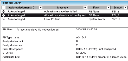
The Diagnostic Viewer uses an instance of a ASI_DIA DFB to display information about AS-Interface bus detected errors.
Diagnostic Viewer illustration:
There are 2 areas in the Diagnostic Viewer:
|
Area
|
AS-Interface Related Description
|
|
Upper
|
List of detected errors with columns:
|
|
Lower
|
Provides details about the error message selected in the upper area:
|


 WARNING