The BMX EIA 0100 module may be installed in any of the positions in the rack except:
-
the positions reserved for the rack power supply modules (marked PS, PS1, and PS2),
-
the positions reserved for extended modules (marked XBE),
-
the positions reserved for the CPU in the main local rack (marked 00 or marked 00 and 01 depending on the CPU),
-
the positions reserved for the (e)X80 adapter module in the main remote drop (marked 00).
NOTE: The module can be mounted and removed no matter the power status of the PLC and AS-Interface bus power supplies (on or off) with no adverse effects on the module or the rack holding it.
Installing the Module on the Rack
The following procedure is for installing the module on a rack.
|
Step
|
Action
|
Illustration
|
|
1
|
Make sure the rack slot cover has been removed from the slot to be used.
|
|
|
2
|
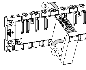
Position the locating pins situated at the rear of the module (on the bottom) in the corresponding slots in the rack.
|
Steps 2 and 3:
|
|
3
|
Swivel the module towards the top of the rack so that the module sits flush with the back of the rack. It is now set in position.
|
|
4
|
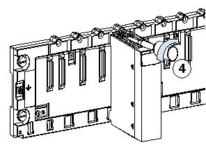
Tighten the retaining screw so that the module is held in place on the rack.
Tightening torque: 0.4...1.5 N•m (0.30...1.10 lbf-ft).
|
|
Maximum Number of Sensor Modules per M340 Station
The maximum number of BMX EIA 0100 modules supported per processor is
-
BMX P34 1000: 2
-
BMX P34 20•0: 4
Maximum Number of Sensor Modules per M580 Station
The maximum number of BMX EIA 0100 modules supported per processor BMX P58 •••• is 4.
The maximum number of BMX EIA 0100 modules supported per (e)X80 adapter module BM• CRA 31210 is 2.

