The registers 3:x (PLC input register) and 4:x (PLC output register) are used to process commands with the ESI module. The x refers to the starting address of the ESI module in the PLC hardware configuration.
The command data processed by the ESI module is placed in the output registers (4:x) and the possible response information is placed in the input registers (3:x).
The following example shows the register occupancy through Command 5, Upload the ESI System Time and Command 6, Set the ESI System Time.
Command 5 is used to upload the system time. For the command to be correctly executed, the command parameter must be written in the Word 0 of the ESI module output register. Word 0 is the first output register in the modules hardware configuration (PLC configuration).
NOTE: When addressing the hardware with the Start address 4:1 to the End address 4:12 in the PLC configuration, command word 0 corresponds to the address 4:1.
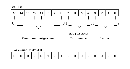
Command word 0 is divided into the following areas:
Description of the command word:
|
Area (Bit)
|
Description
|
Example value
|
|
0 - 3
|
Number of the register to be uploaded or output. The number of the output register (3:x) is defined with command 5. This sets the value 0.
|
0
|
|
4 - 7
|
Port number. The ports are not used when commands 5 or 6 are executed. The data is only processed internally in the module using the register.
|
0
|
|
8 - 15
|
Command designation in Bit format. When the command value is set the command is directly processed.
|
5
|
NOTE: Command 0 can be set with the help of Move-Blocks or by external switches. Other variations are also possible.
As a result of the action the ESI system time data is placed in registers
1 to 7.
Data return is carried out via the PLC 3:x register. It corresponds to the input registers in the modules hardware configuration (PLC configuration)
NOTE: Register 0 (status register) shows the status of the command processing. The register corresponds to command word 0 when the command has been executed correctly. If faulty data occurs, the status of the MSB (Most Significant Bit) changes from 0 to 1.
Command 6 is used to set the system time. As with command 5, the command parameters required must be written to Word 0 of the ESI module output register (4:x). The time and date parameters are additionally transferred when setting the system time. The parameters are placed in the registers following command
word 0.
NOTE: Before setting command word 0 the time and date information must be placed in the corresponding 4:x registers.
The successful execution of the command can be monitored during processing with the help of the status register.
