|
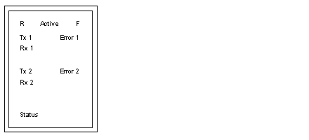
LED Indicators
|
|
|
Original instructions
|

|
LEDs
|
Color
|
Indication
|
|---|---|---|
|
R
|
Green
|
The module has passed power-up diagnostics.
|
|
Active
|
Green
|
Bus communication is present.
|
|
F
|
Red
|
The module has detected a fault.
|
|
RX1
|
Green
|
Received data on RS-232 Port 1
|
|
TX1
|
Green
|
Transmitted data on RS-232 Port 1
|
|
RX2
|
Green
|
Received data on RS-232 Port 2
|
|
TX2
|
Green
|
Transmitted data on RS-232 Port 2
|
|
Status
|
Yellow
|
Status
|
|
Error 1
|
Red
|
There is an error condition on Port 1
|
|
Error 2
|
Red
|
There is an error condition on Port 2
|
|
F
|
Status
|
Error 1
|
Error 2
|
Condition
|
|---|---|---|---|---|
|
Blinking
|
Blinking
|
Blinking
|
Blinking
|
The ASCII module is initializing
|
|
First power-up
|
||||
|
OFF
|
ON
|
OFF
|
OFF
|
Programming mode
|
|
OFF
|
OFF
|
ON
|
N/A
|
Serial Port 1 has incurred a buffer overrun
|
|
OFF
|
OFF
|
N/A
|
ON
|
Serial Port 2 has incurred a buffer overrun
|
|
N/A
|
Blinking (see crash codes)
|
OFF
|
OFF
|
The module is in kernel mode and may have an error
|
|
Number of Blinks
|
Code (in hex)
|
Error
|
|---|---|---|
|
Steady ON
|
0000
|
Requested kernel mode
|
|
4
|
6631
|
Bad microcontroller interrupt
|
|
5
|
6503
|
RAM address test error
|
|
8
|
6402
|
RAM data test error
|
|
7
|
6300
|
PROM checksum error (EXEC not loaded)
|
|
6301
|
PROM checksum error
|
|
|
630A
|
Flash message checksum error
|
|
|
630B
|
Executive watchdog timeout error
|
|
|
8
|
8000
|
Kernel other error
|
|
8001
|
Kernel PROM checksum error
|
|
|
8002
|
Flash program error
|
|
|
8003
|
Unexpected executive return
|