Functional Description
Original instructions
Function
The BMX AMO 0802 is a high density output analog module fitted with 8 non-isolated channels. It offers the following current ranges for each output:
The range is selected during configuration.
Illustration
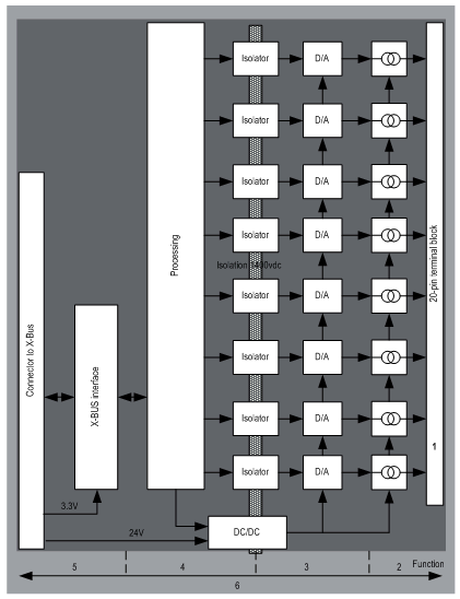
The BMX AMO 0802 module’s illustration is as follows:
Description:
Address
Process
Characteristics
1
Adapting the outputs
  • physical connection to the process through a 20-pin screw terminal block
  • protecting the module against voltage spikes
2
Adapting the signal to the Actuators
  • the adaptation is performed on current via software configuration
3
Converting
  • this conversion is performed on 15 bits with a polarity sign
  • reframing the data provided by the program is performed automatically and dynamically by the converter
4
Transforming application data into data directly usable by the digital/analog converter
  • use of factory calibration parameters
5
Communicating with the Application
  • manages exchanges with CPU
  • topological addressing
  • from the application, receiving the configuration parameters for the module and channels as well as numeric set points from the channels
  • sending module status back to application
6
Module monitoring and sending error notifications back to the application
  • output power supply test
  • testing for range overflow on channels
  • testing for output open circuits and short-circuits
  • watchdog test
  • Programmable fallback capabilities
Writing Outputs
The application must provide the outputs with values in the standardized format: 0 to +10,000 in 0..20 mV and 4..20 mA ranges.
Digital/Analog Conversion
The digital/analog conversion is performed on: 15-bit in 0..20 mA and 4..20 mA ranges.
Overflow Control
Module BMX AMO 0802 only allows an overflow control on current ranges.
The measurement range is divided in three areas:
Description:
Designation
Description
Nominal range
measurement range corresponding to the chosen range
Overflow Area
area located beyond the upper threshold
Underflow Area
area located below the lower threshold
Overflow values for the various ranges are as follows:
Range
BMX AMO 0802
Underflow Area
Nominal Range
Overflow Area
0..20mA
-2,000
-1,001
-1,000
10,300
10,301
10,500
4..20mA
-1,600
-801
-800
10,300
10,301
10,500
You may also choose the flag for an overflow of the range upper value, for an underflow of the range lower value, or for both.
NOTE: Range under/overflow detection is optional.
Fallback/Maintain or Reset Outputs to Zero
If an error is detected, and depending on its seriousness, the outputs:
Various Behaviors of Outputs:
Error
Behavior of Outputs
Task in STOP mode, or program missing
Fallback/Maintain (channel by channel)
Communication interruption
Configuration Error
0 mA (all channels)
Internal Error in Module
Output Value out-of-range (range under/overflow)
Saturated value (channel by channel)
Output open circuit
Maintain (channel by channel)
Module Hot swapping (processor in STOP mode)
0 mA (all channels)
Reloading Program
Fallback or Maintain at current value is selected during the configuration of the module. The fallback value may be modified from the Debug in Control Expert or through a program.
WARNING
UNEXPECTED EQUIPMENT OPERATION
The fallback position should not be used as the sole safety method. If an uncontrolled position can result in a hazard, an independent redundant system must be installed.
Failure to follow these instructions can result in death, serious injury, or equipment damage.
Behavior at Initial Power-Up and When Switched Off.
When the module is switched on or off, the outputs are set to 0 mA.
Actuator Alignment
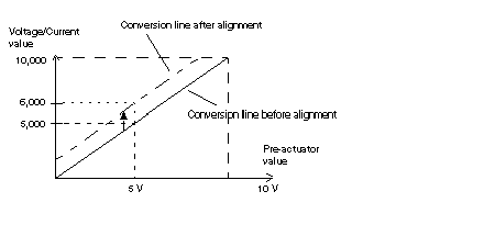
The process of "alignment" consists in eliminating a systematic offset observed with a given actuator, around a specific operating point. This operation compensates for an error linked to the process. Therefore, replacing a module does not require a new alignment. However, replacing the actuator or changing the sensor's operating point does require a new alignment.
Conversion lines are as follows:
The alignment value is editable from a programming console, even if the program is in RUN Mode. For each output channel, you can:
The maximum offset between the measured value and the corrected output value (aligned value) may not exceed +/- 1.500.
NOTE: To align several analog channels on the BMX AMO/AMI/AMM/ART modules, we recommend proceeding channel by channel. Test each channel after alignment before moving to the next channel in order to apply the parameters correctly.