|
|
Original instructions
|
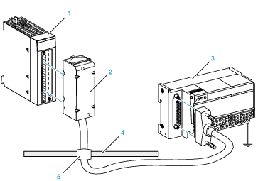
1BMX AMI 0800 module
2BMXFTA••0 connecting cables
3Interface sub-base
4Shield bar
5Clamp

1BMX FTB 2820 Terminal block
2Cable shielding
325-pin Sub-D connector
LLength according to the part number.
|
Characteristic
|
Value
|
|
|---|---|---|
|
Cable
|
Sheath material
|
PVC
|
|
LSZH status
|
No
|
|
|
Environmental
|
Operating temperature
|
-25...70 °C (-13...158 °F)
|
|
TELEFAST terminal block number
|
25-pin Sub-D connector pin number
|
BMXAMI0800 pin out
|
Signal type
|
TELEFAST terminal block number
|
25-pin Sub-D connector pin number
|
BMXAMI0800 pin out
|
Signal type
|
|---|---|---|---|---|---|---|---|
|
1
|
/
|
Ground
|
Supp 1
|
/
|
Ground
|
||
|
2
|
/
|
STD (1)
|
Supp 2
|
/
|
Ground
|
||
|
3
|
/
|
STD (1)
|
Supp 3
|
/
|
Ground
|
||
|
4
|
/
|
STD (2)
|
Supp 4
|
/
|
Ground
|
||
|
100
|
1
|
3
|
+IV0
|
200
|
14
|
2
|
COM0
|
|
101
|
2
|
1
|
+IC0
|
201
|
/
|
Ground
|
|
|
102
|
15
|
4
|
+IV1
|
202
|
3
|
5
|
COM1
|
|
103
|
16
|
6
|
+IC1
|
203
|
/
|
Ground
|
|
|
104
|
4
|
9
|
+IV2
|
204
|
17
|
8
|
COM2
|
|
105
|
5
|
7
|
+IC2
|
205
|
/
|
Ground
|
|
|
106
|
18
|
10
|
+IV3
|
206
|
6
|
11
|
COM3
|
|
107
|
19
|
12
|
+IC3
|
207
|
/
|
Ground
|
|
|
108
|
7
|
17
|
+IV4
|
208
|
20
|
16
|
COM4
|
|
109
|
8
|
15
|
+IC4
|
209
|
/
|
Ground
|
|
|
110
|
21
|
18
|
+IV5
|
210
|
9
|
19
|
COM5
|
|
111
|
22
|
20
|
+IC5
|
211
|
/
|
Ground
|
|
|
112
|
10
|
23
|
+IV6
|
212
|
23
|
22
|
COM6
|
|
113
|
11
|
21
|
+IC6
|
213
|
/
|
Ground
|
|
|
114
|
24
|
24
|
+IV7
|
214
|
12
|
25
|
COM7
|
|
115
|
25
|
26
|
+IC7
|
215
|
/
|
Ground
|
|
|
NOTE: On the ABE-7CPA02, the strap position is between pin 1 and pin 2. +IVx:+ pole voltage input for channel x. +ICx:+ pole current input for channel x. COMx:- pole voltage or current input for channel x. |
|||||||
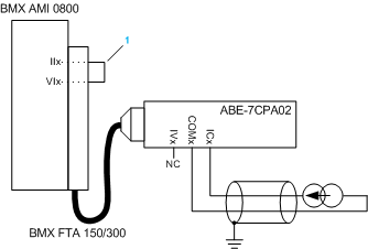
1Strap on the terminal block.
|
NOTICE
|
|
EQUIPMENT DAMAGE
Do not apply a negative current when BMX AMI 0800 is associated with ABE-7CPA03.
Failure to follow these instructions can result in equipment damage.
|
|
TELEFAST terminal block number
|
25-pin Sub-D connector pin number
|
BMXAMI0800 pin out
|
Signal type
|
TELEFAST terminal block number
|
25-pin Sub-D connector pin number
|
BMXAMI0800 pin out
|
Signal type
|
|---|---|---|---|---|---|---|---|
|
1
|
/
|
0 V
|
Supp 1
|
/
|
24 V (sensor supply)
|
||
|
2
|
/
|
0 V
|
Supp 2
|
/
|
24 V (sensor supply)
|
||
|
3
|
/
|
0 V
|
Supp 3
|
/
|
0 V (sensor supply)
|
||
|
4
|
/
|
0 V
|
Supp 4
|
/
|
0 V (sensor supply)
|
||
|
100
|
/
|
+IS1
|
200
|
/
|
+IS0
|
||
|
101
|
15
|
4
|
+IV1
|
201
|
1
|
3
|
+IV0
|
|
102
|
16
|
6
|
+IC1
|
202
|
2
|
1
|
+IC0
|
|
103
|
/
|
Ground
|
203
|
14/3
|
2/5
|
COM0/COM1
|
|
|
104
|
/
|
+IS3
|
204
|
/
|
+IS2
|
||
|
105
|
18
|
10
|
+IV3
|
205
|
4
|
9
|
+IV2
|
|
106
|
19
|
12
|
+IC3
|
206
|
5
|
7
|
+IC2
|
|
107
|
/
|
Ground
|
207
|
17/6
|
8/11
|
COM2/COM3
|
|
|
108
|
/
|
+IS5
|
208
|
/
|
+IS4
|
||
|
109
|
21
|
18
|
+IV5
|
209
|
7
|
17
|
+IV4
|
|
110
|
22
|
20
|
+IC5
|
210
|
8
|
15
|
+IC4
|
|
111
|
/
|
Ground
|
211
|
20/9
|
16/19
|
COM4/COM5
|
|
|
112
|
/
|
+IS7
|
212
|
/
|
+IS6
|
||
|
113
|
24
|
24
|
+IV7
|
213
|
10
|
21
|
+IV6
|
|
114
|
25
|
26
|
+IC7
|
214
|
11
|
23
|
+IC6
|
|
115
|
/
|
Ground
|
215
|
23/12
|
22/25
|
COM6/COM7
|
|
+ISx:24 V channel power supply +IVx:+ pole voltage input for channel x +ICx:+ pole current input for channel x COMx:- pole voltage or current input for channel x |
|||||||
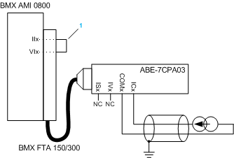
1Strap on the terminal block.
|
TELEFAST terminal block number
|
25-pin Sub-D connector pin number
|
BMXAMI0800 pin out
|
Signal type
|
TELEFAST terminal block number
|
25-pin Sub-D connector pin number
|
BMXAMI0800 pin out
|
Signal type
|
|---|---|---|---|---|---|---|---|
|
1
|
/
|
Ground
|
Supp 1
|
/
|
24 V (sensor supply)
|
||
|
2
|
/
|
Ground
|
Supp 2
|
/
|
24 V (sensor supply)
|
||
|
3
|
/
|
Ground
|
Supp 3
|
/
|
0 V (sensor supply)
|
||
|
4
|
/
|
Ground
|
Supp 4
|
/
|
0 V (sensor supply)
|
||
|
100
|
/
|
+IS0
|
116
|
/
|
+IS4
|
||
|
101
|
1
|
3
|
+IV0
|
117
|
7
|
17
|
+IV4
|
|
102
|
2
|
1
|
+IC0
|
118
|
8
|
15
|
+IC4
|
|
103
|
14
|
2
|
0 V
|
119
|
20
|
16
|
0 V
|
|
104
|
/
|
+IS1
|
120
|
/
|
+IS5
|
||
|
105
|
15
|
4
|
+IV1
|
121
|
21
|
18
|
+IV5
|
|
106
|
16
|
6
|
+IC1
|
122
|
22
|
20
|
+IC5
|
|
107
|
3
|
5
|
0 V
|
123
|
9
|
19
|
0 V
|
|
108
|
/
|
+IS2
|
124
|
/
|
+IS6
|
||
|
109
|
4
|
9
|
+IV2
|
125
|
10
|
23
|
+IV6
|
|
110
|
5
|
7
|
+IC2
|
126
|
11
|
21
|
+IC6
|
|
111
|
17
|
8
|
0 V
|
127
|
23
|
22
|
0 V
|
|
112
|
/
|
+IS3
|
128
|
/
|
+IS7
|
||
|
113
|
18
|
10
|
+IV3
|
129
|
24
|
24
|
+IV7
|
|
114
|
19
|
12
|
+IC3
|
130
|
25
|
26
|
+IC7
|
|
115
|
6
|
11
|
0 V
|
131
|
12
|
25
|
0 V
|
+ISx:24 V channel power supply +IVx:+ pole voltage input for channel x +ICx:+ pole current input for channel x COMx:- pole voltage or current input for channel x. |
|||||||
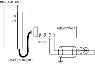
1Strap on the terminal block.
|
TELEFAST terminal block number
|
Terminal
|
Signal type
|
TELEFAST terminal block number
|
Terminal
|
Signal type
|
|---|---|---|---|---|---|
|
1
|
/
|
Ground
|
Supp 1
|
/
|
24 V (sensor supply)
|
|
2
|
/
|
Ground
|
Supp 2
|
/
|
24 V (sensor supply)
|
|
3
|
/
|
Ground
|
Supp 3
|
/
|
0 V (sensor supply)
|
|
4
|
/
|
Ground
|
Supp 4
|
/
|
0 V (sensor supply)
|
|
100
|
/
|
+IS0
|
116
|
/
|
+IS4
|
|
101
|
/
|
T0
|
117
|
/
|
T4
|
|
102
|
/
|
+IC0
|
118
|
/
|
+IC4
|
|
103
|
/
|
0V0
|
119
|
/
|
0V4
|
|
104
|
/
|
+IS1
|
120
|
/
|
+IS5
|
|
105
|
/
|
T1
|
121
|
/
|
T5
|
|
106
|
/
|
+IC1
|
122
|
/
|
+IC5
|
|
107
|
/
|
0V1
|
123
|
/
|
0V5
|
|
108
|
/
|
+IS2
|
124
|
/
|
+IS6
|
|
109
|
/
|
T2
|
125
|
/
|
T6
|
|
110
|
/
|
+IC2
|
126
|
/
|
+IC6
|
|
111
|
/
|
0V2
|
127
|
/
|
0V6
|
|
112
|
/
|
+IS3
|
128
|
/
|
+IS7
|
|
113
|
/
|
T3
|
129
|
/
|
T7
|
|
114
|
/
|
+IC3
|
130
|
/
|
+IC7
|
|
115
|
/
|
0V3
|
131
|
/
|
0V7
|
+ISx:24 V channel power supply Tx:Reserved test pin for HART function, it's internally connected with +ICx +ICx:+ pole current input for channel x COMx:- pole voltage or current input for channel x |
|||||
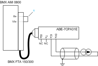
1Strap on the terminal block.