|
|
Original instructions
|

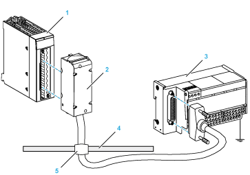
1BMX AMI 0410 module
2BMX FCA ••0 connecting cable
3ABE-7CPA410 interface sub-base
4Shield bar
5Clamp
|
Channels to channels isolation
|
750 Vdc
|
|
Channels to 24Vdc supply isolation
|
750 Vdc
|
|
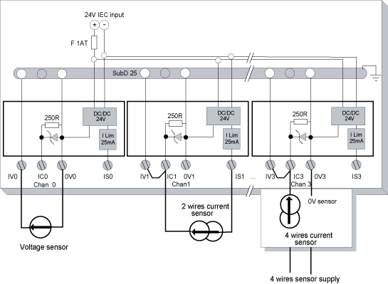
Overvoltage protection on current inputs
|
By Zener diodes 8,2V
|

1BMX FTB 2020 Terminal block
2Cable shielding
325-pin Sub-D connector
LLength according to the part number.
|
Characteristic
|
Value
|
|
|---|---|---|
|
Cable
|
Sheath material
|
PVC
|
|
LSZH status
|
No
|
|
|
Environmental
|
Operating temperature
|
-25...70 °C (-13...158 °F)
|
|
TELEFAST terminal block number
|
25-pin Sub-D connector pin number
|
Signal type
|
TELEFAST terminal block number
|
25-pin Sub-D connector pin number
|
Signal type
|
|---|---|---|---|---|---|
|
1
|
/
|
Earth
|
/
|
|
24 VDC Input
|
|
2
|
/
|
Earth
|
/
|
|
24 VDC Input
|
|
3
|
/
|
Earth
|
/
|
|
0V24 Input
|
|
4
|
/
|
COM 0
|
/
|
0V24 Input
|
|
|
100
|
|
Output IS 0
|
101
|
14
|
COM 0V0
|
|
102
|
|
Output IS 1
|
103
|
3
|
COM 0V1
|
|
104
|
|
Output IS 2
|
105
|
17
|
COM 0V2
|
|
106
|
|
Output IS 3
|
107
|
6
|
COM 0V3
|
|
200
|
1
|
Output IV 0
|
201
|
|
Input IC 0
|
|
202
|
15
|
Output IV 1
|
203
|
|
Input IC 1
|
|
204
|
4
|
Output IV 2
|
205
|
|
Input IC 2
|
|
206
|
18
|
Output IV 3
|
207
|
|
Input IC 3
|
