|
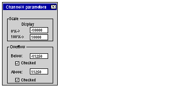
Selecting the Overflow Control Function
|
|
|
Original instructions
|
|
Step
|
Action
|
|---|---|
|
1
|
Access the hardware configuration screen for the appropriate module.
|
|
2
|
Click in the cell of the Scale column for the channel you wish to configure.
Result: an arrow appears.
|
|
3
|
Click on the arrow in the cell of the Scale column for the channel you wish to configure.
Results : The Channel Parameters dialog box appears.
 |
|
4
|
Check the Checked box of the Underflow field to specify an underflow threshold.
|
|
5
|
Check the Checked box of the Overflow field to specify an overflow threshold.
|
|
6
|
Confirm your changes by closing the dialog box
|
|
7
|
Validate the change by clicking Edit → Validate.
|
|
Bit Name
|
Flag (when = 1)
|
|---|---|
|
%IWr.m.c.1.5
|
The value being read falls within the Lower Tolerance Area.
|
|
%IWr.m.c.1.6
|
The value being read falls within the Upper Tolerance Area.
|
|
%IWr.m.c.2.1
|
If over/underflow control is required, this bit indicates that the value currently read falls within one of the two unauthorized ranges:
|
|
%Ir.m.c.ERR
|
Channel Error.
|