Module Configuration
Original instructions
At a Glance
The application used here as an example manages liquid levels in a tank. The tank is filled by a pump and drained using a valve. The different levels of the tank are measured with sensors placed above the tank. The tank should not be filled with more than 100 liters of liquid.
Once the tank is full, the pump stops, and the operator drains the tank manually.
This application requires the use of a BMX AMI 0410 analog input module and a BMX AMO 0210 analog output module. This application may also require a BMX AMM 0600 input/output module.
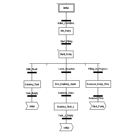
Tank Management Grafcet
The application’s grafcet is as follows:
Using the Measurements
We are going to configure the BMX_AMI_0410 analog input module so that we can retrieve the level of the liquid in the tank.
Step
Action
1
In the Project browser and in Variables & FB instances, double-click on Elementary variables.
2
Create the INT-type variable, Level.
3
In the Address column, enter the address associated with this variable.
In our example, we consider that the sensor is connected to channel 0 of the BMX AMI 0410 module. This module is in turn connected to slot 1 of rack 0. We therefore have the following address: %IW0.1.0.
Illustration:
This variable can be used to check whether the level of liquid in the tank has reached maximum level.
To do this, the following line of code can be associated with the Level_Reached transition of the grafcet.
If the level of liquid in the tank reaches or exceeds the maximum level, the Level_Reached transition is enabled.
Using the Statuses
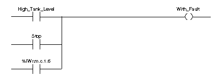
We will need to program the With_fault transition so that we can stop the pump in three cases:
Before we can use the bit, which will indicate whether the measure still falls within the upper tolerance area (%IWr.m.c.1.6), we need to define the display format and scale of the channel used.
Step
Action
1
Access the hardware configuration screen for the appropriate module.
2
4
Access the Parameters dialog box for the channel in order to input the following parameters:
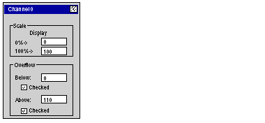
The upper tolerance area will be between 100 and 110 liters.
5
Confirm your changes by closing the dialog box.
6
Validate the change with Edit->Validate.
The code associated with the fault control transition looks like this: