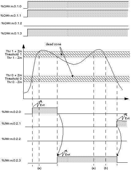
The TSX AEY 420 module manages 2 thresholds per channel (thresholds 0 and 1).
When any one (or several) of these thresholds are crossed, the module may trigger event processing.
A neutral zone around the thresholds is used to avoid accidentally triggering the event if the analog measurement fluctuates around the thresholds.
You have the option of associating an event processing action to an analog channel during the module's
software configuration.
The event is triggered if:
-
measurement becomes less than (Threshold 0 – Neutral zone),
-
measurement becomes greater than (Threshold 0 + Neutral zone),
-
measurement becomes less than (Threshold 1 – Neutral zone),
-
measurement becomes greater than (Threshold 1 + Neutral zone).
Event causes may be masked or validated through programming, using bits from the word %QWr.m.c:
|
Address
|
Function (0 = mask, 1 = validate)
|
|
%QWr.m.c.1.0
|
Crossing over (above) Threshold 0.
|
|
%QWr.m.c.1.1
|
Crossing over (below) Threshold 0.
|
|
%QWr.m.c.1.2
|
Crossing over (above) Threshold 1.
|
|
%QWr.m.c.1.3
|
Crossing over (below) Threshold 1.
|
Bits from the %IWr.m.c.2 word indicate the root cause of the event:
|
Address
|
Function (1 = event, 0 = no event).
|
|
%IWr.m.c.2.0
|
Crossing over (above) Threshold 0.
|
|
%IWr.m.c.2.1
|
Crossing over (below) Threshold 0.
|
|
%IWr.m.c.2.2
|
Crossing over (above) Threshold 1.
|
|
%IWr.m.c.2.3
|
Crossing over (below) Threshold 1.
|
The following example shows detection on channel 0 of crossings:
The crossing of threshold 1 when rising is masked. The triggering of the associated event is therefore not activated (case a).
The %IWr.m.c.2 input word is updated only when a new event cause appears (case b).
When the measured value is equal to the threshold but does not cross over, no event is triggered.
Event processing may be enabled or disabled by configuring each channel.
An event number (from 0 to 63) is assigned to each channel. The choice of number determines the event priority (0 = maximum priority, 1 to 63 = lower priority).
Value of the Neutral Zone
The neutral zone is the area around each threshold (0 and 1). Its value depends on the configured measurement range and scale used. It cannot be modified by the user. The intervals of the neutral zone are:
-
(+Zm) which is added to each of the thresholds (0 and 1),
-
(-Zm) which is subtracted from each of the thresholds (0 and 1).
The following table shows the values (+/-Zm) of the neutral zone according to the measurement range and type of scale used:
|
|
Range
|
|
+/- 10V
|
0..10V
|
0..5V and
0..20 mA
|
1..5V and
4..20mA
|
|
Standardized scale
|
3
|
3
|
6
|
7
|
|
User scale
|
|
|
|
|
|
|
|
Legend
|
|
(1): Δrange = Upper range threshold – Lower range threshold
|
Example of calculating the neutral zone:
For a 0..10 V range where the configured user scale is -5000/5000.
Δrange = 5000 -(-5000) =10000
The value of +Zm and -Zm will therefore be 3.


