The size and number of racks and the kinds of modules installed on the racks are significant considerations when you are planning an installation. That installation may be either inside or outside an enclosure. The height, width, and depth of the installed system head as well as the spacing between the local and the extender racks need to be well understood.
Modules such as the power supply, CPU, and I/O are cooled by natural convection.
To maintain the necessary thermal cooling, respect the:
Correct Mounting Position
The Modicon X80 racks must be mounted horizontally on a vertical plane to facilitate ventilation.
NOTE: Other rack mounting positions may cause overheating and unexpected equipment operation.
Clearance Around the Racks
When you are planning the clearance around the racks, you need to consider the overall size of your Modicon X80 I/O platform.
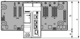
Add additional clearance at the bottom of the rack to accommodate the height of modules higher than the racks such as M580 CPU or redundant power supplies.
The following figure shows an example with an M580 CPU:
a
Additional space below the rack to accommodate the height of the CPU.
b
The height of the rack.
c
Overall height is 134.6 mm (5.299 in.).
NOTE: Add additional clearance of 1.2 mm (0.05 in.) at the right of the rack if you plan to install a rack extender module.
Thermal Considerations Inside an Enclosure
For non-vented equipment mounted inside a cabinet, cooled by natural air convection, the ambient temperature is the air temperature at a point not more than 50 mm (1.97 in.) and not less than 25 mm (0.98 in.) away from the equipment, on a horizontal plane located at the vertical mid-point below the equipment.
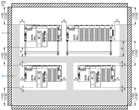
For optimal cooling and air circulation, an adequate clearance must be respected between your Modicon X80 I/O platform and surrounding objects (such as wire ducts, inside surface of an enclosure, machinery).
This illustration shows the rules of a typical installation in a cabinet with ducts:
1
installation or casing
2
wiring duct or tray
a
side clearance: > 40 mm (1.57 in.)
b
top and bottom clearance with surrounding objects: > 20 mm (0.79 in.)
NOTE:
In order to rise the density, a lower spacing between racks is acceptable if:
-
there is no shielding bar, nor ducts between racks
-
the spacing between racks is not lower than 40 mm (1.57 in.)
-
you apply a 5 °C (9 °F) derating to the maximum ambient temperature allowed. That is 55 °C (131 °F) for standard and coated modules versions and 65 °C (149 °F) for hardened modules.
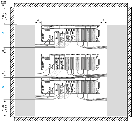
This illustration shows the rules of an installation in a cabinet without horizontal ducts between two racks:
1
installation or casing
2
wiring duct or tray
a
side clearance: > 40 mm (1.57 in.)
c
top and bottom clearance between two racks: > 40 mm (1.57 in.)
The cables pass by the front of the PLC to join the vertical ducts on the side of the cabinet.
NOTE: As the shielding bar accessory is removed, the EMC protection (shields of cables clamping to earth) shall be done on copper bars located at the arrival of cables from field, usually at the bottom of the cabinet.
Clearance for Cable Installation
When you plan to install the racks inside an enclosure, leave a minimum space in front of the modules.The dimensions of each type of X80 modules are provided in
Appendix B.
The minimum depth of the enclosure is:
NOTE: If BMXXBE1000 rack extender modules are connected, the use of BMXXBC•••K cables with connectors angled at 45° is recommended.
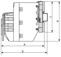
Here is a side view of a rack on a DIN rail with modules and cables mounted in an enclosure:
a
wiring + module + backplane depth: > 200 mm (7.874 in.)
b
wiring + module + backplane + DIN rail depth: > 210 mm (8.268 in.)
c
rack height
d
module height  WARNING
 WARNING

