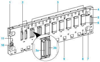
1
Panel mounting hole (x4)
2
Power supply module slot connectors
3
Module slot connectors
3a
Ethernet connector (depending on reference)
3b
X bus connector
4
Tapped hole for locking screw on each module
5
40-pin female connector for a rack extender module
6
Protective cap
7
Screw hole (X2) for shielding connection kit
8
Keying hole for Ethernet module (depending on reference)
9
Holes for anchoring the module pins
10
Protective earth screw
11
Rack status LED (depending on reference)
NOTE: The rack is supplied with covers that protect the connectors against moisture and dust. The covers must be removed before installing the modules.
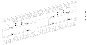
The following figure shows the DIN-rail locking mechanism at the rear of the Modicon X80 racks:
1
Upper locking
2
Spring
1
Lower locking
NOTE: The 10-slot (BMEXBP1002(H)) and 12-slot (BMXXBP1200(H) and BMEXBP1200(H)) racks do not have springs like the ones shown in the legend (item 2). These racks cannot be mounted on a DIN rail.
The power supply slots are located the furthest left on the Modicon X80 racks.
Each power supply slot has two connectors marked:
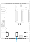
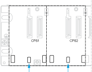
The size of the center hole for anchoring the power supply modules on the racks is different depending on type of rack. This mechanical keying prevents from inserting standalone power supply module on redundant power supply racks. Conversely, you can install a redundant power supply module on standalone power supply racks.
|
Standalone power supply racks:
|
Redundant power supply racks:
|
|
|
|
NOTE: Power supply slots are reserved for the power supply modules, and no other module types can be installed here.
Exception: You can install BMXCPS4002 power supply modules only on the following dual-bus racks (Ethernet and X bus):
The module slots, which are to the right of one or two power supply slots, are labeled numerically starting at 00.
The number of module slots, and the presence or absence of an Ethernet connector at each module slot, depends on the
Modicon X80 rack reference.
Some modules (such as M580 CPUs, eX80 modules, and so on) have a pin at the rear side to prevent from inserting it in an unsupported Modicon X80 rack. For example, installing an M580 CPU on an X bus rack requires a BMXXBP•••• (PV0.2 or later) rack.
Refer to the documentation of the module to check module and rack compatibility.
Rack Extender Module Slot
The module slot labeled XBE (rightest module slot of the rack) is not a standard module slot. It is reserved for a BMXXBE1000 rack extender module. No other module type can be installed in the XBE slot.
Ethernet and X bus Connections
All Modicon X80 racks have an X bus connector at every module slot. Many X80 I/O modules need only X bus to support communication across the backplane.
An Ethernet communication bus is embedded in the backplane of the BMEXBP••00 and BMEXBP••02 racks.
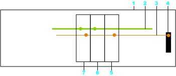
This illustration shows an example of module connections with a BMEXBP•••• rack:
1
Rack
2
Ethernet communication bus on the backplane
3
X bus communication bus on the backplane
4
X bus extender connector
5
Modicon X80 module
6
Ethernet only module
7
Module with Ethernet and X bus connectors
NOTE: The X bus extender connector is only linked to the X bus backplane.
A green status LED marked OK is present on Ethernet racks but not on X bus racks. The LED indicates if the rack is working properly.
When this LED is ON, these conditions (which are internal to the rack) have been fulfilled:
-
The power rail voltages are in the rated range.
-
The X bus diagnostic is working properly.
-
The Ethernet switch diagnostic is working properly.
When the LED is OFF, the backplane is not operational.
