|
Configuring STB NIP 2212 Properties
|
|
|
(Original Document)
|

|
Step
|
Action
|
|
|---|---|---|
|
1
|
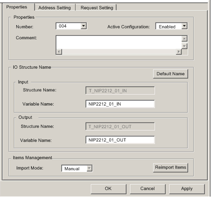
In the Properties section of the page, edit the following:
|
|
|
Number
|
The relative position of the device in the list, from 0...127.
For this example, accept the default of 004.
|
|
|
Active Configuration
|
Accept the default setting of Enabled.
|
|
|
2
|
In the IO Structure Name section of the page, edit the following:
|
|
|
Input area:
|
||
|
Structure Name
|
(Read-only) Control Expert automatically assigns a structure name based on the variable name, in this case T_NIP2212_01_IN.
|
|
|
Variable Name
|
Accept the auto-generated variable name (based on the alias name): NIP2212_01_IN.
|
|
|
Output area:
|
||
|
Structure Name
|
(Read-only) Control Expert automatically assigns a structure name based on the variable name, in this case T_NIP2212_01_OUT.
|
|
|
Variable Name
|
Accept the auto-generated variable name (based on the alias name): NIP2212_01_OUT.
|
|
|
Default Name button
|
Restores the default variable and structure names. For this example, custom names are used.
|
|
|
3
|
In the Items Management section of the page, edit the following:
|
|
|
Import mode
|
In this example, select Manual.
|
|
|
Reimport Items
|
Imports the I/O items list from the device DTM, overwriting any manual I/O item edits. Enabled only when Import mode is set to Manual.
|
|
|
4
|
Click Apply to save your edits, and leave the window open for further edits.
|
|

|
Step
|
Action
|
|
|---|---|---|
|
1
|
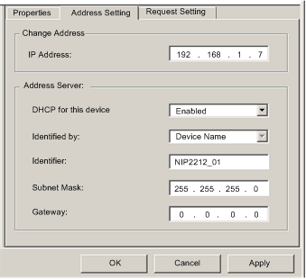
In the Address Settings page, edit the following:
|
|
|
IP Address
|
By default:
In this example, the IP address is 192.169.1.7.
|
|
|
DHCP for this Device
|
Select Enabled.
|
|
|
Identified by
|
If DHCP for this Device is Enabled, this indicates the device identifier type:
Select Device Name.
|
|
|
Identifier
|
If DHCP for this Device is Enabled, the specific device MAC Address or Name value.
Type in NIP2212_01.
|
|
|
Mask
|
The device subnet mask. The default = 255.255.255.0.
Accept the default value.
|
|
|
Gateway
|
The gateway address used to reach this device. The default of 0.0.0.0 indicates this device is located on the same subnet as the Ethernet communication module.
Accept the default value.
|
|
|
2
|
Click Apply to save your edits, and leave the window open for further edits.
|
|

|
Step
|
Action
|
|
|---|---|---|
|
1
|
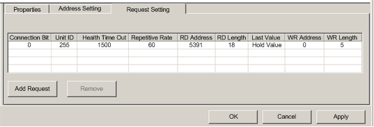
In the Request Settings page, edit the following:
|
|
|
Connection Bit
|
(Read-only) The offset for both the health bit and the control bit for this connection. Offset values are auto-generated by the Control Expert Ethernet Configuration Tool—starting at 0—based on the connection type, in the following order:
1. Modbus TCP connections
2. Local Slave connections
3. EtherNet/IP connections
NOTE: When this Modbus TCP connection is created, the offset values for the previously created local slave and EtherNet/IP connections are incremented by 1: the local slave connection bit is set to 1, and the EtherNet/IP connection bit value is set to 2. |
|
|
Unit ID
|
The number of the device, or module, that is the target of the connection. A value of:
NOTE: When accessing data in the Ethernet communication module itself, use 255. When accessing data in the application running in the PLC, use a value from 0 to 254 (a value of 1 is recommended). Because the remote device itself is the request target, accept the default value of 255.
|
|
|
Health Timeout
|
The maximum allowed period, in milliseconds, between device responses, from 0...120000 ms in increments of 5 ms. When this setting is exceeded, the health timeout bit is set to 1. The default = 1500 ms. Accept the default value of 1500.
|
|
|
Repetitive Rate
|
The data scan rate, from 0...60000 ms, in intervals of 5 ms. The default = 60 ms. Accept the default value of 60.
|
|
|
RD Address
|
Address in the remote device of the input data image. The input data image begins at word 45391. Because there is an offset of 40000 in the Premium platform, type in a value of 5391.
|
|
|
RD Length
|
The number of words in the remote device, from 0...125, that the communication module will read. Because the Modbus device will be configured for 18 words of input items, type in a value of 18.
|
|
|
Last Value
|
The behavior of inputs in the application in the event communication is lost:
Accept the default.
|
|
|
WR Address
|
Address in the remote device of the output data image. The output data image begins at word 40000. Because there is an offset of 40000 in the Premium platform, type in a value of 0.
|
|
|
WR Length
|
The number of words in the remote device, from 0 to 120, to which the communication module will write. Because the Modbus device will be configured for 5 words of output items, type in a value of 5.
|
|
|
2
|
Click OK to save your edits, and close the window.
|
|