Configuring Explicit Messaging Using SEND_REQ
Original instructions
Overview
Use the SEND_REQ function block to configure EtherNet/IP connected and unconnected explicit messages. The SEND_REQ block can:
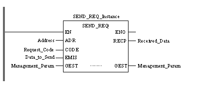
The Management_Param, Data_to_Send, and Received_Data parameters define the operation. Refer to Configuring the Management Parameter, Configuring the Data to Send Parameter, and Contents of the Received Data Parameter, below, for details.
EN and ENO can be configured as additional parameters.
FBD Representation
LD Representation
IL Representation
LD Address
SEND_REQ Request_Code, Data_to_Send, Management_Param, Received_Data
ST Representation
SEND_REQ (Address, Request_Code, Data_to_Send, Management_Param, Received_Data);
Input Parameters
Parameter
Data type
Description
Address
Array [0...5] of INT
The path to the destination device.
Request_Code
INT
Always 0x0E (for a CIP request).
Data_to_Send
Array [n...m] of INT
The message type (connected or unconnected) plus the CIP request.
Input/Output Parameters
Parameter
Data type
Description
Management_Param
Array [0...3] of INT
The management parameter, consisting of 4 words.
Output Parameters
Parameter
Data type
Description
Received_Data
Array [n...m] of INT
The CIP response.
Configuring the Address Parameter
To configure the Address parameter, use the ADDR function to convert a character string to an address, as follows:
ADDR(‘{network.station}rack.module.channel.destination address’)
NOTE:
  • The Xway address elements {network.station} are required only when bridging through another PLC station.
  • The channel parameter value is always 0.
Configuring the Management Parameter
The Management Parameter consists of 4 contiguous words, as described below:
Data source
Register
Description
High Byte (MSB)
Low Byte (LSB)
Data managed by the system
Management_Param[0]
Exchange number
Activity Bit (bit 0)
(see below).
Management_Param[1]
Data managed by the user
Management_Param[2]
Block timeout. Values include:
  • 0 = infinite wait
  • other values = timeout x 100 ms, for example:
    • 1 = 100 ms
    • 2 = 200 ms
    • ...etc.
Management_Param[3]
Length of data send/receive parameter:
  • Input (before send): length of Data_to_Send parameter
  • Output (after receive): length of Received_Data parameter
Activity Bit:
This bit indicates the execution status of the communication function.
It is set to 1 when launched, and returns to 0 when its execution is complete.
It is the first bit of the first element of the table.
Example: if the management table has been declared as follows:
Tab_Gest ARRAY [0.3] OF INT,
the activity bit is the bit with the notation Tab_Gest[1].0.
NOTE: The notation previously used requires configuration of the project properties in such a way as to authorize the extraction of bits on integer types. If this is not the case, Tab_Gest[1].0 cannot be accessed in this manner.
Configuring the Data_to_Send Parameter
The Data_to_Send parameter varies in size. It consists of contiguous registers that include—in sequence—both the message type and the CIP request:
Content
Length
Byte Offset
Data Type
Description
Message Type
1 word
0
INT
  • 0 = unconnected message
  • 1 = connected message
CIP Request1
Set by Management_Param[3] (size of Data_to_Send)
2
Byte
Service: the service performed by the explicit message.
3
Byte
Request_Path_Size: the number of words in the Request_Path field.
4
Byte Array
Request_Path: The path of the request—including class ID, instance ID, etc.—for this transaction.
...
Byte Array
Request_Data: Service specific data to be delivered in the explicit message request—if none, this field is empty
1 
The CIP request must be structured in little endian order.
Contents of the Received_Data Parameter
The Received_Data parameter contains only the CIP response. The length of the CIP response varies, and is reported by Management_Param[3] after the response is received. The format of the CIP response is described, below:
Byte offset
Field
Data type
Description
0
Reply Service
Byte
Service of the explicit message + 0x80
1
Reserved
Byte
0
2
General Status
Byte
EtherNet/IP General Status
3
Size of Additional Status
Byte
Additional Status array size—in words
4
Additional Status
Byte array
Additional status
...
Response Data
Byte array
Response data from request, or additional error data if General Status indicates an error
NOTE: The response must be structured in little endian order.