|
Configuring Local Slave Properties: The General page
|
|
|
Original instructions
|
|
Step
|
Action
|
|---|---|
|
1
|
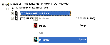
In the Devices window, right click on the EtherNet/IP Local Slave icon, then select Properties in the popup menu.
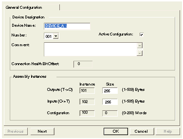
 The General page of the Local Slave properties window opens.
|
|
2
|
Enter settings (refer to the table below) for the following parameters to configure local slave functionality for the EtherNet/IP module.
 Note: When using explicit messaging to read the EtherNet/IP module’s assembly object, be sure to allocate sufficient room for the response, because the size of the response will equal the sum of:
the size of the assembly + Reply service (1 byte) + General Status (1 byte)
Local slave properties are described, below.
|
|
3
|
The next task is to configure slave inputs and outputs.
|
|
Setting
|
Description
|
|---|---|
|
Device Designation section:
|
|
|
Active Configuration
|
In this example, this setting is selected.
|
|
Device Name
|
Assign the local slave a unique name, consisting of up to 32 characters, including numbers, letters, and the underscore character.
In this example, the auto-generated name DEVICE_A is accepted.
|
|
Number
|
The unique number—or identifier—assigned to the device.
In this example, select the number 001.
|
|
Comment
|
User-defined free text comment area. 80 characters maximum. In this example, leave blank.
|
|
Connection Health Bit Offset
|
Auto-generated integer (0...127) indicating the offset of the connection’s health bit in the status byte array of the input area.
Note: This setting is auto-generated only when the local slave settings are input and the network configuration is saved.
|
|
Assembly Instances section:
|
|
|
Outputs T -> O Instance
|
A read-only value always set to 101.
|
|
Outputs T -> O Size
|
The maximum size reserved for local slave outputs, in bytes. An integer from 0...509. In this example, accept the default of 256.
|
|
Inputs O -> T Instance
|
A read-only value always set to 102.
|
|
Inputs O -> T Size
|
The maximum size reserved for local slave inputs, in bytes. An integer from 0...509. In this example, accept the default of 256.
|
|
Configuration Instance
|
A read-only value always set to 103.
|
|
Configuration Size
|
A read-only value always set to 0.
|