Overview
Certain devices can be configured in depth by using a device type manager (DTM).
DTMs are managed in the Topology Manager where they can be opened and configured.
A certain number of DTMs are provided with Control Expert but you can add additional ones to the local DTM catalog. These DTMs can be used, for example, with generic devices or slave devices on a fieldbus.
Only one user can edit parameters in the DTM of a device at a time. While a DTM is open, editing attributes of the device in the pane is not allowed.
You may be able to deploy and load the DTM configuration to and from a device.
Prerequisites
To be used, the DTM of a device must be created on the local computer and the local DTM updated.
DTM Window
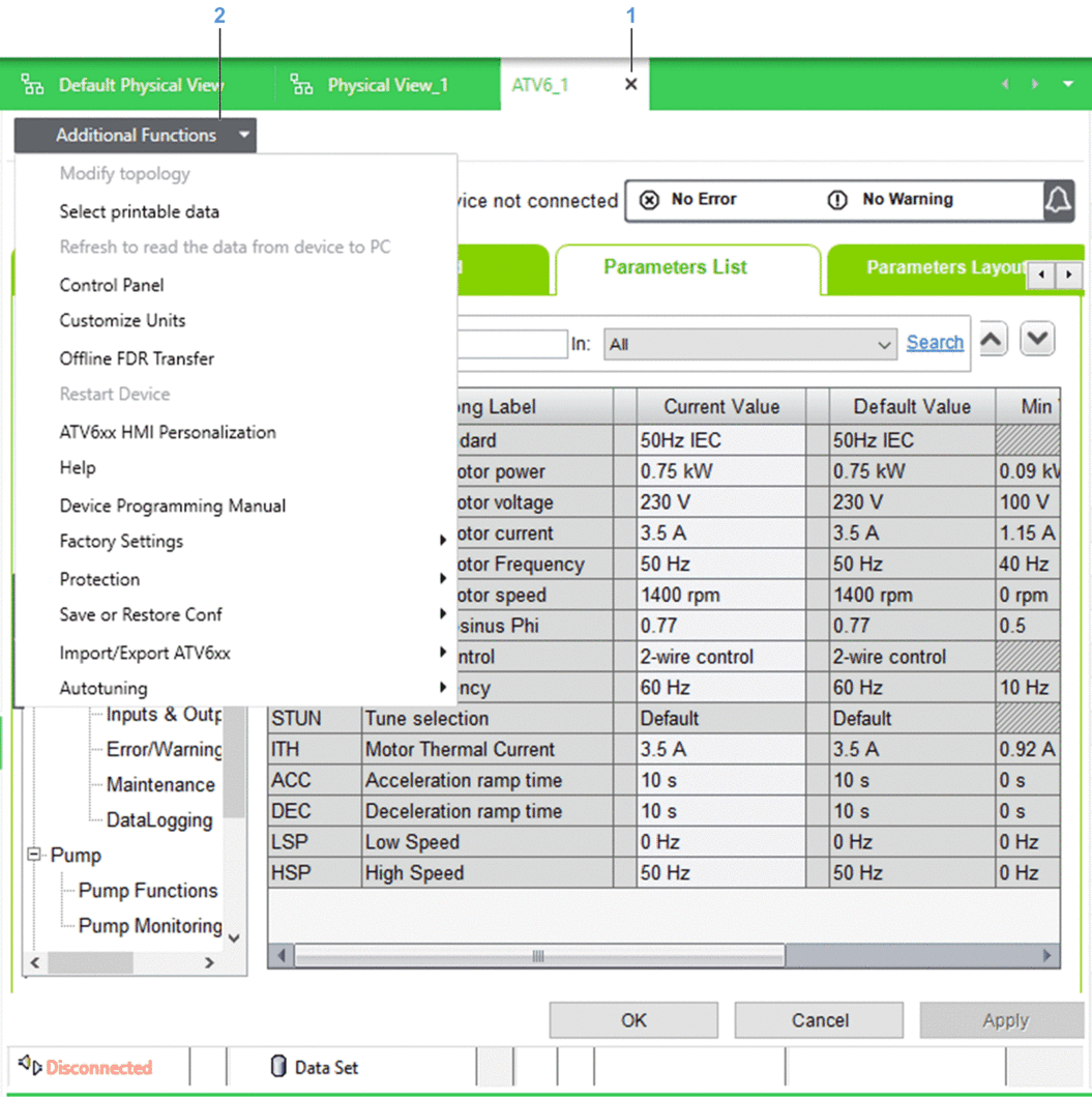
The following figure shows an example of DTM window that opens when you use the command of the device context menu. In the example, the menu is expanded to show the additional DTM commands that are available while the device is disconnected.

Item |
Description |
|---|---|
1 |
Button to close the DTM. |
2 |
Menu that lets you access quickly, various additional functions that are featured by the DTM. The content of the menu is DTM-specific. The availability of commands depends on the connection state of the device. That is, when the device is disconnected, commands that require the device to be connected are shown disabled, and vice versa. |
Placeholder DTMs in the Control Project
When a device that is configured by using a DTM is scanned by using an I/O scanner, a corresponding DTM appears in the connectivity tree of the when you edit the control project.
This DTM is only a placeholder for the DTM of the device, which you need to manage from the device in the Topology Manager.
File Types Used to Create DTMs
DTMs can be created by using the following types of files.
File type |
Description |
|---|---|
Executable |
The installation method of the DTM is defined by the device manufacturer. |
EDS |
This file type is used for EtherNet/IP devices and requires using an installation tool. |
GSD |
This file type is used for PROFIBUS devices and requires using an installation tool. |
FdtDTM Settings
The section of the window lets you configure the following:
Which network adapter of the computer is used to connect to a device.
The path where the installation tool for EDS and GSD files is located.
Managing EDS Files
The table describes the commands of the submenu in the toolbar of the Topology Manager.
Command |
Description |
|---|---|
|
Opens a wizard that lets you add a DTM to the by using an EDS file. |
|
Opens a wizard that lets you remove a DTM from the by removing the corresponding EDS file. |
|
Lets you create an export file, which contains the EDS files of the local EDS library. |
|
Lets you import an EDS library to the local computer. |
Managing GSD Files
The table describes the commands of the submenu in the toolbar of the Topology Manager.
Command |
Description |
|---|---|
|
Opens a wizard that lets you add a DTM to the by using a GSD file. |
|
Opens a wizard that lets you remove a DTM from the by removing the corresponding GSD file. |
(1) |
Opens a wizard that lets you export to a library file (.glb) the GSD files that are installed on the local computer at a path that you select. You can enter the name and location of the GSD library export file. |
(1) |
Opens a wizard that lets you import the content of a GSD library export file (.glb) to the local computer. |
(1) Requires that the PRM Gateway DTM version 1.3.2.0 or later is installed on the computer. Verify that in the window is configured with the path where the PRM Gateway DTM has installed the tool. |
|
Device Properties to Be Configured Outside of the DTM
You need to configure the values of the following attributes of the device by using the pane.
The table describes which values are propagated to the DTM and their state depending on the type of DTM that the device uses.
Attribute configured in the pane |
Third-party DTM |
Schneider Electric DTM |
|---|---|---|
Device and |
Values are propagated and are read-only. |
Values are propagated and are read-only. |
Communication card (if applicable) |
||
(1) |
Not propagated. |
|
(1) |
Value is propagated and remains editable(2). |
Values are propagated if supported by the DTM and are read-only. |
(1) |
Values are not propagated. |
|
(1) |
||
DHCP configuration information(1) |
||
(1) For embedded interfaces of the device and its communication cards (if applicable). (2) The values in pane and in the DTM need to be identical. |
||
Pasting and Importing Devices That Use a DTM
When you configure parameters inside the DTM of a device and cut, copy, or export this device, the values that you have configured are retained when you paste or import the device.
Opening the DTM of a Device and Editing Values
Step |
Action |
|---|---|
1 |
Right-click the device and select . Result: The DTM opens in a new window. |
2 |
Edit values as required and apply them (if applicable). |
3 |
Close the DTM from its tab. Result: Depending on the DTM, the DTM closes and changes are saved or a confirmation dialog box opens, which prompts you to save changes before closing. |


