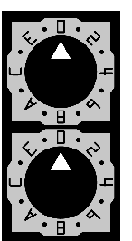
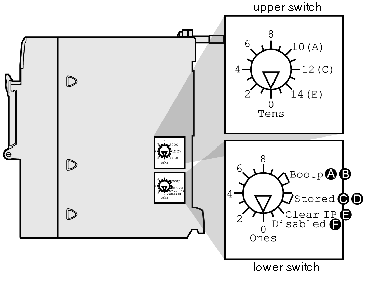
The BMX NOE 01•0 or BMX P34 20x0 operates as a single node on an and possibly other networks. The module must have a unique IP address. The two rotary switches on the back of the module provide a simple way to select an address:
NOTE: Set the arrow firmly into the desired position. If you do not feel the switch click into place, the value of the switch may be incorrect or undetermined.
Summary of Valid IP Address Settings
Each rotary switch position that you can use to set a valid IP address is marked on the module. The following information summarizes the valid address settings:
-
device name: For a switch-set device name, select a numeric value from 00 to 159. You can use both switches:
-
On the upper switch (Tens digit), the available settings are 0 to 15.
-
On the lower switch (Ones digit), the available settings are 0 to 9.
The device name is calculated from the sum of the two switch values. For example, a BMX P34 2020 CPU with the switch setting in the above figure is assigned the DHCP device name BMX_2020_123.
The selection on the lower switch of any non-numeric (BOOTP, STORED, CLEAR IP, DISABLED) makes the setting on the upper switch inconsequential.
-
BOOTP: To get an IP address from a BOOTP server, select either of the two BOOTP positions on the bottom switch.
-
STORED: The device uses the application’s configured (stored) parameters.
-
CLEAR IP: The device uses the default IP parameters.
-
DISABLED: The device does not respond to communications.
To assist you in setting the rotary switches to their proper positions, a label is affixed to the right side of the module. The switch settings are described in this table:
|
|
Upper Switch
|
|
0 to 9: Tens value for the device name (0, 10, 20 . . . 90)
|
|
10(A) to 15(F): Tens value for the device name (100, 110, 120 . . . 150)
|
|
Lower Switch
|
|
0 to 9: Ones value for the device name (0, 1, 2 . . . 9)
|
|
BOOTP: Set the switch to A or B to receive an IP address from a BOOTP server.
|
|
Stored: Set the switch to C or D to use the application’s configured (stored) parameters.
|
|
Clear IP: Set the switch to E to use the default IP parameters.
|
|
Disabled: Set the switch to F to disable communications.
|

