|
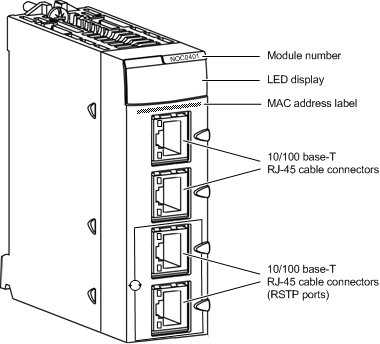
Physical Description of the BMX NOC 0401 Module
|
|
|
Original instructions
|


|
Setting
|
Description
|
|---|---|
|
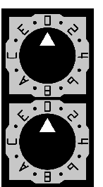
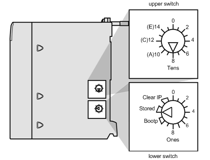
Upper switch:
|
|
|
0...9
|
Tens value (0, 10, 20...90) for the device name setting. It is added to the ones value on the lower switch to identify the module to a DHCP server.
|
|
A...F
|
Tens value (100, 200, 300...150) for the device name setting. It is added to the ones value on the lower switch to identify the module to a DHCP server.
|
|
Lower switch:
|
|
|
0...9
|
Ones value (0, 1, 2...9) for the device name setting. It is added to the tens value on the upper switch to identify the module to a DHCP server.
|
|
A + B
|
BootP1:The module obtains its IP address from a BootP server.
|
|
C + D
|
Stored1: The module uses the IP address configured in the application.
|
|
E + F
|
Clear IP1: The module applies its default IP address.
|
|
1. The lower switch alone determines module behavior. The upper switch is ignored.
|
|
