Control Expert assigns a located address in %MW memory to each input and output variable for a remote device and local slave, when that device or slave is activated.
In addition, Control Expert removes from %MW memory each located variable address whenever the related device or slave is de-activated.
Because activating and de-activating devices can cause substantial changes to located variable addresses, Schneider Electric recommends the following practices:
-
Activate every device and local slave your application is likely to use, and allow these devices to remain activated.
-
-
When configuring function blocks in Control Expert, instead of directly reassigning input and output pins to a specific %MW address, do the following: assign specific input and output pins only to the derived data types and variables automatically created by Control Expert.
The sample network is a part of the same physical network that has been the subject of our continuing configuration example, and includes:
-
the Ethernet communication module, named NOC01
-
an STB NIC 2212 EtherNet/IP network interface module with I/O modules, named NIC2212_01
Note that, when a new network is created, Control Expert presents three local slave nodes that can be activated and pre-assigns them device numbers 000, 001, and 002. By default, each local slave is not activated. Therefore, each local slave’s inputs and outputs are not initially assigned a %MW memory address.
The following example describes the effect of activating a local slave function after another remote device has already been configured and added to the network. In this ca
The sample Ethernet network has been configured as follows:
-
Total network inputs and outputs are set in the Configuration page of the Ethernet communication module in Control Expert:
-
100 input words are reserved, beginning at %MW01
-
100 output words are reserved, beginning at %MW101
-
Connection bits for the project include:
-
Local slave inputs and outputs include:
-
Remote EtherNet/IP device inputs and outputs include:
I/O Assignment Without an Activated Local Slave
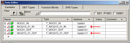
When you click the Update application button in the Ethernet communication module Configuration page, with the local slave de-activated, Control Expert auto-generates a collection of variables in support of the application’s I/O items at the following instance locations:
Note the address locations of the remote EtherNet/IP device’s inputs (%MW17) and outputs (%MW117). As you will see, below, when the local slave is activated, these address locations will change.
I/O Assignment With an Activated Local Slave
The following example displays input and output variables for the same project. However, in this example the
Active Configuration setting for the first local slave was set to
Enabled in the
local slave configuration page, before the input and output variables were created. As a result clicking the
Update application button in the Ethernet communication module
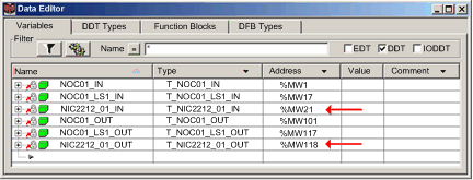
Configuration page generated the following collection of variables:
Notice how the address locations for the remote EtherNet/IP device have shifted:
This shift of %MW input and output memory address assignments occurs because the local slave was activated, and local slave I/O variables are placed in a located memory address position ahead of remote EtherNet/IP device I/O variables.
A similar shift of addresses would occur—with respect to both local slave and EtherNet/IP device I/O variable addresses—if a Modbus TCP remote device is activated. This is because Modbus TCP device I/O variables are places in a located memory address position ahead of both local slave and EtherNet/IP I/O variables.
As stated above, a way to avoid this shift of I/O memory addresses is to activate every local slave and remote device that your project may require, and then allow them to remain active. To later disable a device, use the appropriate control bits to toggle off every connection to that device.

