|
|
Original instructions
|
|
Network
|
NOP IP Address (ETH2/3)
|
IED IP Address
|
IED Gateway IP Address
|
|---|---|---|---|
|
2
|
192.168.2.1/24
|
192.168.2.2/24 – 192.168.2.254/24
|
192.168.2.1
|
|
3
|
192.168.3.1/24
|
192.168.3.2/24 – 192.168.2.254/24
|
192.168.3.1
|
|
4
|
192.168.4.1/24
|
192.168.4.2/24 – 192.168.2.254/24
|
192.168.4.1
|

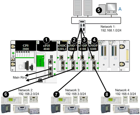
1A BME•58•••• CPU connects the local rack to the main ring.
2A BMENOP0300 module is connected to: A) the control network (network 1) via port ETH1 and 6) network 2 via port ETH3.
3A BMENOP0300 module is connected to: A) the control network (network 1) via port ETH1 and 7) network 3 via port ETH3.
4A BMENOP0300 module is connected to: A) the control network (network 1) via port ETH1 and 8) network 4 via port ETH3.
5On network 1 (control network), with the network address of 192.168.1.0, a PC uses the IP address 192.168.1.0/24.
6network 2 with the address 192.168.2.0/24
7network 3 with the address 192.168.3.0/24
8network 4 with the address 192.168.4.0/24