Introduction to Transparency
You can segregate a network into multiple subnetworks to limit user access and increase performance. This usually means that devices in different subnetworks are not able to communicate directly.
You can, however, use the
IP forwarding functionality to enable Ethernet network transparency to facilitate seamless communications between devices in different subnetworks. This topic describes an example of IP forwarding supported by the BMENOP0300 module.
Before you start this example, change your Control Expert configuration to facilitate the use of the IP forwarding service:
Suppose you want to provide transparency between two networks:
-
On network 1, with the network address of 10.10.0.0, host A (a PC) uses the IP address 10.10.0.1.
-
On network 3, with the network address 172.16.0.0, host C (an IED) uses the IP address 172.16.0.1.
To facilitate communications between hosts A and C, connect the networks 1 and 3 both physically and logically. The IP forwarding service in the BMENOP0300 module is the interface for these network connections.
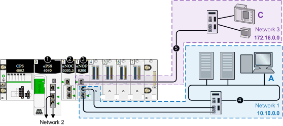
In the following sample architecture, the IP forwarding service in the BMENOP0300 module provides transparency between these two networks. Host A in subnetwork 10.10.0.0 (blue) can communicate with host C in subnet 172.16.0.0 (purple) because the BMENOP0300 module is configured with an IP address in each of the two networks.
1
A BME•58•••• CPU connects the local rack to the main ring.
2
A BMENOP0300 Ethernet communication module is connected to the CPU over the Ethernet backplane (and is therefore on the same network at the CPU).
3
The IP forwarding service of the BMENOP0300 Ethernet communication module has IP addresses in two subnetworks: network 1 (10.10.0.0) and network 3 (172.16.0.0).
4
Network 1, in subnetwork 10.10.0.0, includes a PC (host A).
5
Network 3, in subnetwork 172.16.0.0, includes IEDs.
In this example, the IP forwarding service of the BMENOP0300 module has two interfaces with different IP addresses in two subnetworks:
|
Network
|
IP Forwarding Service
|
|
IP Address
|
Sub-Network Mask
|
Network Address
|
Ethernet Interface
|
|
network 1
|
10.10.0.1
|
255.255.0.0
|
10.10.0.0
|
ETH 2, ETH 3
|
|
network 3
|
172.16.0.1
|
255.255.0.0
|
172.16.0.0
|
ETH 1
|
Now that you have established the IP forwarding service, add the IP address forwarding information to the PC (host A), the IEDs (host C), which allows the hosts to send packets beyond their own subnetworks by utilizing the IP forwarding service of the BMENOP0300 module.
-
Configure the IEDs (host C) to forward all traffic that is destined for outside its subnetwork to the BMENOP0300 module. That is, confirm that all traffic for networks other than 172.16.0.0 is forwarded to the appropriate interface of the BMENOP0300 module.
-
Also configure the PC (host A) in a similar way. However, in a PC environment, it is possible to configure distinct rules about communications. To facilitate communications between the example PC in the network 1 and the devices in network 3, set the IP address of the BMENOP0300 module in network 1 as the route for traffic that is destined for network 3.
NOTE: The connections of network 1 and network 3 to the BMENOP0300 module, could be swapped, depending on which network requires the RSTP protocol.
